AD8271 Ver la hoja de datos (PDF) - Analog Devices
Número de pieza
componentes Descripción
Fabricante
AD8271 Datasheet PDF : 20 Pages
| |||
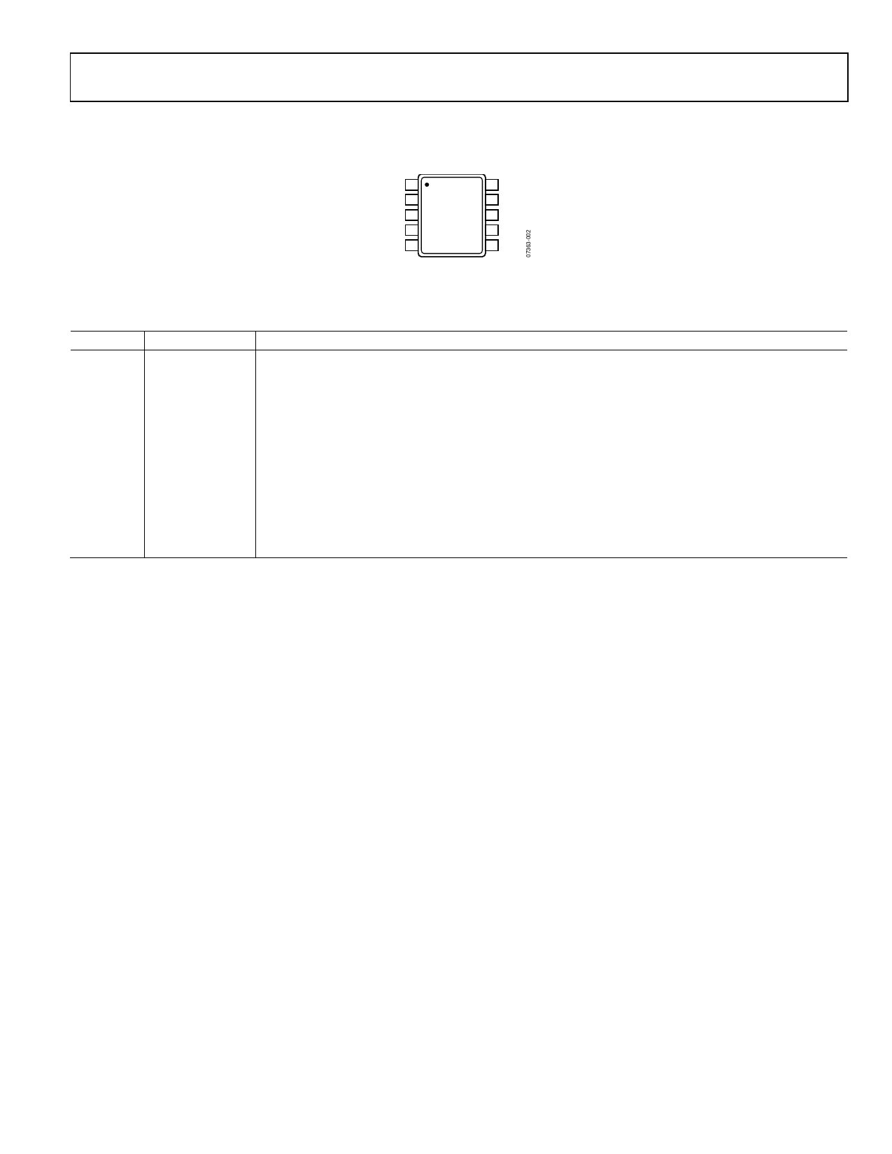
PIN CONFIGURATION AND FUNCTION DESCRIPTION
AD8271
P1 1
P2 2
P3 3
P4 4
–VS 5
10 N3
AD8271
TOP VIEW
(Not to Scale)
9 N2
8 N1
7 OUT
6 +VS
Figure 3.
Table 7. Pin Function Descriptions
Pin No. Mnemonic
Description
1
P1
Noninverting Input. A 10 kΩ resistor is connected to the noninverting (+) terminal of the op amp.
2
P2
Noninverting Input. A 10 kΩ resistor is connected to the noninverting (+) terminal of the op amp.
3
P3
Noninverting Input. A 20 kΩ resistor is connected to the noninverting (+) terminal of the op amp. This pin
is used as a reference voltage input in many configurations.
4
P4
Noninverting Input. A 20 kΩ resistor is connected to the noninverting (+) terminal of the op amp. This pin
is used as a reference voltage input in many configurations.
5
−VS
Negative Supply.
6
+VS
Positive Supply.
7
OUT
Output.
8
N1
Inverting Input. A 10 kΩ resistor is connected to the inverting (−) terminal of the op amp.
9
N2
Inverting Input. A 10 kΩ resistor is connected to the inverting (−) terminal of the op amp.
10
N3
Inverting Input. A 10 kΩ resistor is connected to the inverting (−) terminal of the op amp.
Rev. 0 | Page 7 of 20
Share Link: 