HV3418X Ver la hoja de datos (PDF) - Supertex Inc
Número de pieza
componentes Descripción
Fabricante
HV3418X Datasheet PDF : 5 Pages
| |||
HV3418
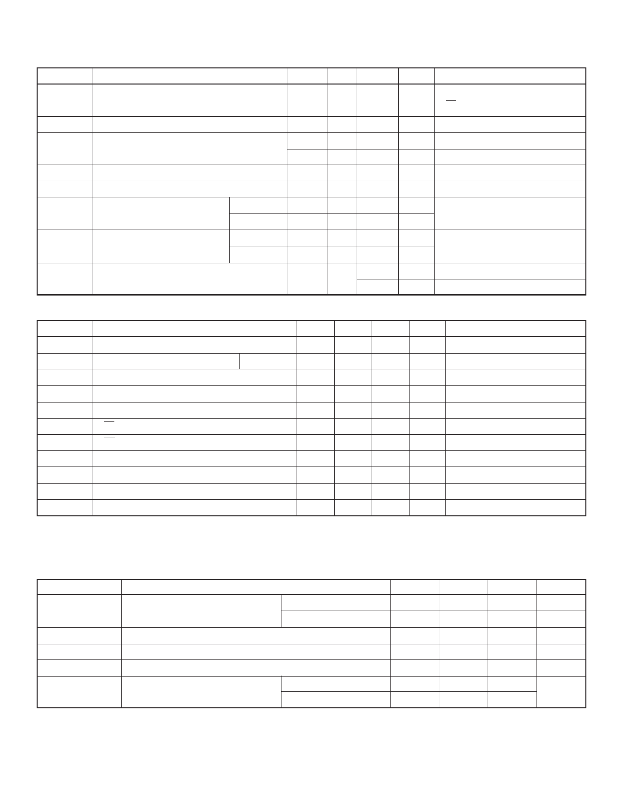
Electrical Characteristics (over recommended operating conditions unless noted)
DC Characteristics
Symbol
Parameter
Min Typ Max Units
Conditions
IDD
VDD Supply Current
25
mA
fCLK = 12MHz, fDATA = 12MHz
LE = LOW
IDDQ
Quiescent VDD Supply Current
200
µA
All VIN = 0V or VDD
IPP
High Voltage Supply Current
0.50
mA
VPP = 180V All outputs high
0.50
mA
VPP = 180V All outputs low
IIH
High-Level Logic Input Current
10
µA
VIH = VDD
IIL
Low-Level Logic Input Current
-10
µA
VIL = 0V
VOH
High-Level Output
HVOUT
155
V
VPP = 180V, IHVOUT = -5mA
Data Out VDD -1V
V
IDOUT = -100µA
VOL
Low-Level Output
HVOUT
25
V
VPP = 180V, IHVOUT = +5mA
Data Out
1.0
V
IDOUT = +100µA
VOC
HVOUT Clamp Voltage
VPP +1.5 V
IOL = +5mA
-1.5
V
IOL = -5mA
AC Characteristics1,2 (For VDD = 12V: values in parentheses are for VDD = 5V; VPP = 180V, TA = 25°C)
Symbol
Parameter
Min Typ Max Units
Conditions
fCLK
Clock Frequency
tW
Clock Width High and Low
High
40(83)
tSU
Data Setup Time Before Clock Rises
25(35)
tH
Data Hold Time After Clock Rises
10(30)
tWLE
Width of Latch Enable Pulse
62(80)
tDLE
LE Delay Time Rising Edge of Clock
25(35)
tSLE
LE Setup Time Before Rising Edge of Clock 30(40)
tON, tOFF
Time from Latch Enable to HVOUT
tDHL
Delay Time Clock to Data High to Low
tDLH
Delay Time Clock to Data Low to High
tr, tf
All Logic Inputs
Notes:
1. Shift register speed can be as low as DC as long as Data Set-up and Hold Time meet the spec.
2. AC Characteristics are guaranteed only under VDD = 12V and VDD = 5V.
12(6)
1(1.5)
50(110)
75(160)
5
MHz
ns
ns
ns
ns
ns
ns
µs
ns
ns
ns
CL = 20pF
CL = 20pF
CL = 20pF
Recommended Operating Conditions
Symbol
Parameter
Min
Typ
VDD
Logic supply voltage
VDD = 5V
VDD =12V
V
High voltage supply
PP
VIH
High-level input voltage
VIL
Low-level input voltage
TA
Operating free-air temperature
Plastic
Ceramic
4.5
10.8
60
VDD -0.9
0
-40
-55
5.0
12.0
Notes:
Power-up sequence should be the following:
1. Connect ground.
2. Apply VDD.
3. Set all inputs (Data, CLK, Enable, etc.) to a known state.
Power-down sequence should be the reverse of the above.
4. Apply VPP.
5. The VPP should not drop below VDD or float during operation.
Max
5.5
13.2
180
VDD
0.9
+85
+125
Units
V
V
V
V
V
°C
2
Share Link: 