DK2416FCK Ver la hoja de datos (PDF) - Dynex Semiconductor
Número de pieza
componentes Descripción
Fabricante
DK2416FCK Datasheet PDF : 13 Pages
| |||
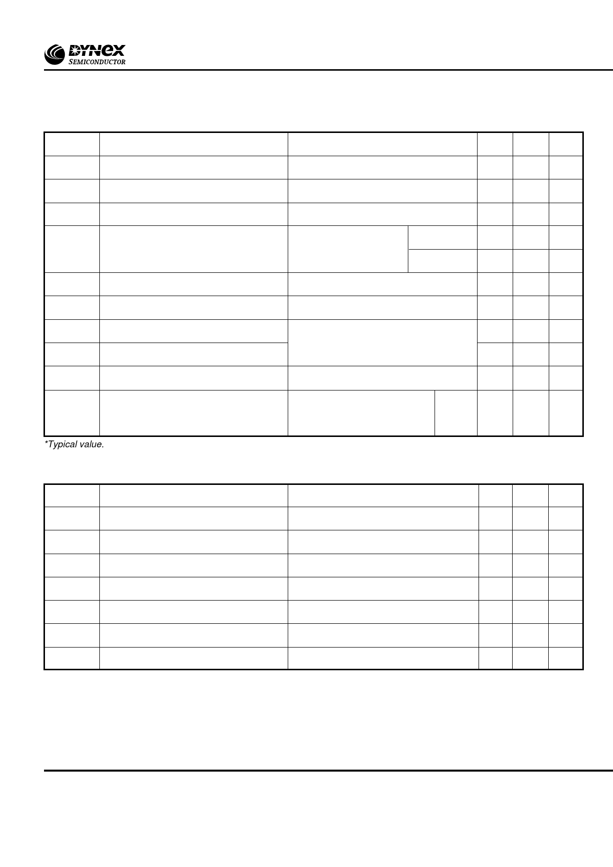
DK24..FC
DYNAMIC CHARACTERISTICS
Symbol
Parameter
Conditions
Min.
VTM
Maximum on-state voltage
At 450A peak, Tcase = 25oC
-
IRRM/IDRM Peak reverse and off-state current
At VRRM/VDRM, Tcase = 125oC
-
dV/dt Maximum linear rate of rise of off-state voltage Linear to 60% VDRM Tj = 125oC, Gate open circuit -
dI/dt Rate of rise of on-state current
Gate source 20V, 20Ω
t
r
<
0.5µs,
T
j
=
125˚C
Repetitive 50Hz -
Non-repetitive -
VT(TO)
Threshold voltage
At Tvj = 125oC
-
rT
On-state slope resistance
At Tvj = 125oC
-
tgd
t(ON)TOT
Delay time
Total turn-on time
T = 25˚C, I = 50A,
j
T
1.5*
VD = 300V, IG = 1A,
dI/dt = 30A/µs, dIG/dt = 1A/µs
3*
I
Holding current
H
T = 25oC, I = 1A, V = 12V
-
j
TM
D
tq
Turn-off time
*Typical value.
Tj = 125˚C, IT = 200A, VR =
dV/dt = 200V/µs (Linear to
50V,
60%
VDRM),
tq
code:
C
-
dIR/dt = 30A/µs, Gate open circuit
Max. Units
2.0
V
25 mA
200 V/µs
500 A/µs
800 A/µs
1.25 V
1.66 mΩ
-
µs
-
µs
70 mA
50
µs
GATE TRIGGER CHARACTERISTICS AND RATINGS
Symbol
Parameter
VGT
IGT
VGD
V
RGM
IFGM
PGM
PG(AV)
Gate trigger voltage
Gate trigger current
Gate non-trigger voltage
Peak reverse gate voltage
Peak forward gate current
Peak gate power
Mean gate power
Conditions
VDRM = 12V, Tcase = 25oC, RL = 6Ω
VDRM = 12V, Tcase = 25oC, RL = 6Ω
At VDRM Tcase = 125oC, RL = 1kΩ
Anode positive with respect to cathode
Typ. Max. Units
-
3.0
V
-
200 mA
-
0.2
V
-
5.0
V
-
4
A
-
16
W
-
3.0
W
3/13
www.dynexsemi.com
Share Link: 