MP03TT580-16-W1 Ver la hoja de datos (PDF) - Dynex Semiconductor
Número de pieza
componentes Descripción
Fabricante
MP03TT580-16-W1 Datasheet PDF : 9 Pages
| |||
MP03TT580
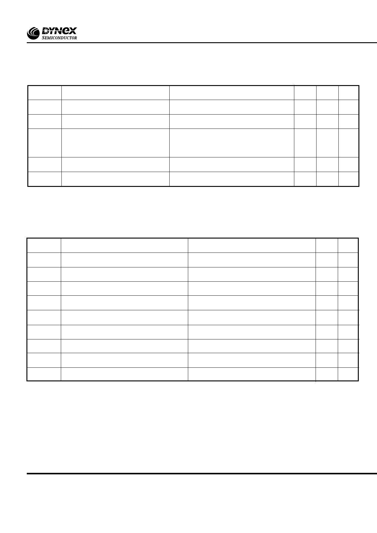
DYNAMIC CHARACTERISTICS
Symbol
Parameter
Test Conditions
Min. Max. Units
IRRM/IDRM Peak reverse and off-state current
At
VRRM/VDRM,
T
j
=
125˚C
-
300 mA
dV/dt Linear rate of rise of off-state voltage
To 67% VDRM, Tj = 125˚C
-
1000 V/µs
dI/dt
Rate of rise of on-state current
From 67% VDRM to 500A, gate source 10V, 5Ω
-
150 A/µs
t
r
=
0.5µs,
T
j
=
125˚C
VT(TO)
Threshold voltage
At Tvj = 125˚C
-
0.98 V
r
On-state slope resistance
T
At Tvj = 125˚C
-
0.75 mΩ
Note : The data given in this datasheet with regard to forward voltage drop is for calculation of the power dissipation in the
semiconductor elements only. Forward voltage drops measured at the power terminals of the module will be in excess of these
figures due to the impedance of the busbar from the terminal to the semiconductor.
GATE TRIGGER CHARACTERISTICS AND RATINGS
Symbol
Parameter
VGT
I
GT
VGD
VFGM
VFGN
VRGM
IFGM
PGM
P
G(AV)
Gate trigger voltage
Gate trigger current
Gate non-trigger voltage
Peak forward gate voltage
Peak forward gate voltage
Peak reverse gate voltage
Peak forward gate current
Peak gate power
Mean gate power
Test Conditions
VDRM = 5V, Tcase = 25oC
VDRM = 5V, Tcase = 25oC
At VDRM Tcase = 125oC
Anode positive with respect to cathode
Anode negative with respect to cathode
-
Anode positive with respect to cathode
See table fig. 5
-
Max. Units
3
V
150 mA
0.25 V
30
V
0.25 V
5
V
10
A
100 W
5
W
3/9
www.dynexsemi.com
Share Link: 