TDA18271HD Ver la hoja de datos (PDF) - NXP Semiconductors.
Número de pieza
componentes Descripción
Fabricante
TDA18271HD Datasheet PDF : 70 Pages
| |||
NXP Semiconductors
TDA18271HD
Silicon Tuner IC
The RF tracking filters central frequency can be adjusted with the tuning word
RFC_CPROG. The RF tracking filter calibration (RFCAL) uses an internal tone at the
input of the tracking filters (generated by CAL PLL) and finds the RFC_CPROG that
corresponds to the maximum transmitted power. The RFCAL is just a small part of a more
complex algorithm fully described in the flowcharts in Section 9.4.
The Power detection mode is a Normal mode in which the detector used for the
calibrations is switched ON. This special mode enables power sensing at the input of the
TDA18271HD and makes the power scan algorithm possible (see Section 9.4.8
“Flowchart TDA18271PowerScan”).
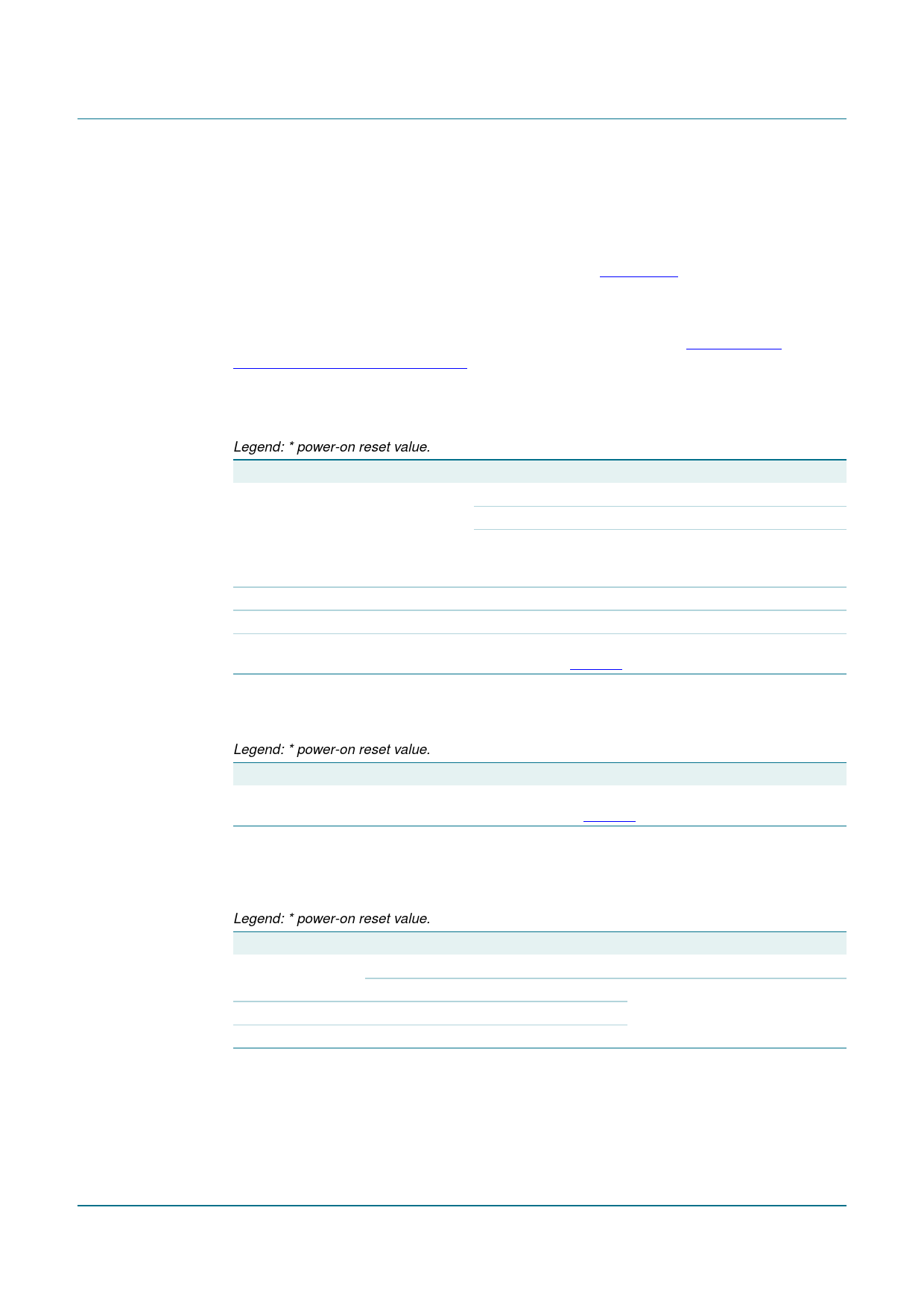
9.3.9 Description of Easy prog byte 5
Table 19. EP5 - Easy prog byte 5 (subaddress 07h) bit description
Legend: * power-on reset value.
Bit Symbol
Access Value Description
7
EXTENDED_REG R/W
enables extended register addressing
1
extended register (10h to 26h)
0*
limited register (00h to 0Fh); only 1 byte can
be programmed after address 0Fh within 1
transmission
6 to 4 IR_GSTEP[2:0] R/W 011* gain step for image rejection calibration
3
-
R/W 0*
must be set to logic 0
2 to 0 IR_MEAS[2:0]
R/W 000* image rejection measurement frequency range
(see Table 53)
9.3.10 Description of Cal post-divider byte
Table 20. CPD - Cal post-divider byte (subaddress 08h) bit description
Legend: * power-on reset value.
Bit Symbol
Access Value Description
7 to 0 CAL_POST_DIV[7:0]
R/W
00h* calibration synthesizer post-divider (see
Table 48)
9.3.11 Description of Cal divider bytes 1, 2 and 3
Table 21. CD1, CD2 and CD3 - Cal divider bytes 1, 2 and 3 (address 09h, 0Ah and 0Bh) bit
description
Legend: * power-on reset value.
Address Register Bit Symbol
Access Value Description
09h
CD1
7
-
R/W 0* must be set to 0
6 to 0 CAL_DIV[22:16] R/W 00h* calibration synthesizer main
0Ah
CD2
7 to 0 CAL_DIV[15:8] R/W 00h* divider bits
0Bh
CD3
7 to 0 CAL_DIV[7:0] R/W 00h*
TDA18271HD_4
Product data sheet
Rev. 04 — 19 May 2009
© NXP B.V. 2009. All rights reserved.
18 of 70
Share Link: 