HG74ALVC162835C Ver la hoja de datos (PDF) - Hyundai Micro Electronics
Número de pieza
componentes Descripción
Fabricante
HG74ALVC162835C Datasheet PDF : 8 Pages
| |||
18-BIT UNIVERSAL BUS DRIVER
WITH 3-STATE OUTPUTS
HG74ALVC162835C
Jan. 1999
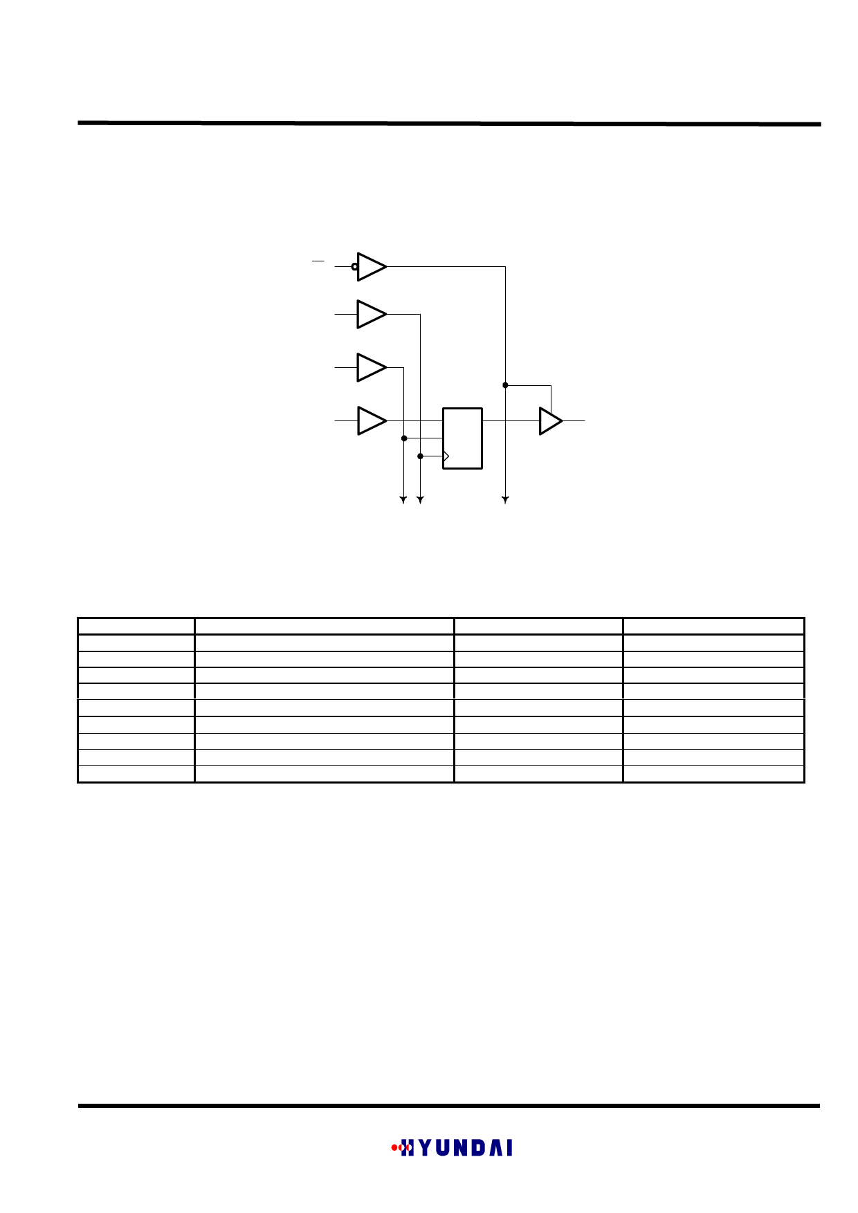
Logic Diagram (positive logic)
27
OE
30
CLK
28
LE
54
A1
1D
C1
CLK
TO 17 Other Channels
3
Y1
Absolute Maximum Ratings Over Operating Free-air Temperature Range=
Symbols
VCC
VI
VO
IIK
IOK
IO
ICC
IGND
Tstg
Parameter
Supply Voltage Range
Input Voltage Range (see note 1)
Output Voltage Range (see notes 1 and 2)
Input Clamp Current
Output Clamp Current
Continuous Output Current
Continuous Current through each VCC
Continuous Current through each GND
Storage Temperature Range
Value
-0.5 V to 4.6 V
-0.5 V to VCC + 0.5 V
-0.5 V to VCC + 0.5 V
-50 mA
±50 mA
±50 mA
+100 mA
-100 mA
- 65°C to 150°C
Conditions
VI < 0
VO <0 or VO >VCC
VO =0 to VCC
=Stresses beyond those listed under “ absolute maximum rating” may cause permanent damage to the device. These are stress ratings only, and
functional operation of the device at these or any other conditions beyond those indicated under “recommended operating condition” is not
implied. Exposure to absolute maximum-rated conditions for extended periods may affect device reliability.
Note 1) The input and output voltage ratings may be exceeded if the input and output clamp current are observed.
Note 2) This value is limited to 4.6 V maximum.
Copyright ©1999, Hyundai Electronics Industries Co., Ltd.
ELECTRONICS
Share Link: 