MAX691AD Ver la hoja de datos (PDF) - Maxim Integrated
Número de pieza
componentes Descripción
Fabricante
MAX691AD Datasheet PDF : 16 Pages
| |||
Microprocessor Supervisory Circuits
WDI
RESET 15
MAX691A
MAX693A
TO µP RESET
1k
R–F—iE—gS—uEr—eT–
1.
is
Adding an external pull-down
valid with VCC down to GND.
resistor
ensures
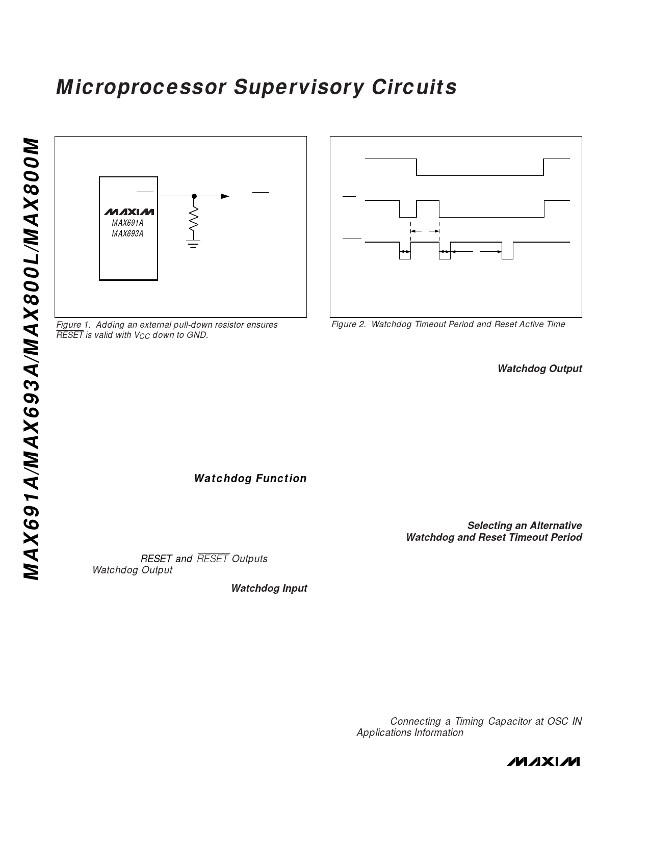
WDO
RESET
t2
t1
t1
t3
t1 = RESET TIMEOUT PERIOD
t2 = NORMAL WATCHDOG TIMEOUT PERIOD
t3 = WATCHDOG TIMEOUT PERIOD IMMEDIATELY AFTER RESET
Figure 2. Watchdog Timeout Period and Reset Active Time
RESET and RESET are asserted when VCC falls below
the reset threshold (4.65V for the MAX691A/MAX800L,
4.4V for the MAX693A/MAX800M) and remain asserted
for 200ms typ after VCC rises above the reset threshold
on power-up (Figure 5). The devices’ battery-
switchover comparator does not affect reset assertion.
However, both reset outputs are asserted in battery-
backup mode since VCC must be below the reset
threshold to enter this mode.
Watchdog Function
The watchdog monitors µP activity via the Watchdog
Input (WDI). If the µP becomes inactive, RESET and
RESET are asserted. To use the watchdog function,
connect WDI to a bus line or µP I/O line. If WDI
remains high or low for longer than the watchdog time-
out period (1.6sec nominal), WDO, RESET, and RESET
are asserted (see RESET and RESET Outputs section,
and the Watchdog Output discussion on this page).
Watchdog Input
A change of state (high to low, low to high, or a mini-
mum 100ns pulse) at the WDI during the watchdog
period resets the watchdog timer. The watchdog
default timeout is 1.6sec.
To disable the watchdog function, leave WDI floating.
An internal resistor network (100kΩ equivalent imped-
ance at WDI) biases WDI to approximately 1.6V.
Internal comparators detect this level and disable the
watchdog timer. When VCC is below the reset thresh-
old, the watchdog function is disabled and WDI is dis-
connected from its internal resistor network, thus
becoming high impedance.
Watchdog Output
The Watchdog Output (WDO) remains high if there is a
transition or
period. The
pulse at WDI during
watchdog function is
the watchdog
disabled and
W–timDeOouist
a logic high when VCC is below the reset threshold, bat-
tery-backup mode is enabled, or WDI is an open circuit.
In watchdog mode, if no transition occurs at WDI during
the watchdog timeout period, RESET and RESET are
asserted for the reset timeout period (200ms typical).
WDO goes low and remains low until the next transition
at WDI (Figure 2). If WDI is held high or low indefinitely,
RESET and RESET will generate 200ms pulses every
1.6sec. WDO has a 2 x TTL output characteristic.
Selecting an Alternative
Watchdog and Reset Timeout Period
The OSC SEL and OSC IN inputs control the watchdog
and reset timeout periods. Floating OSC SEL and OSC
IN or tying them both to VOUT selects the nominal 1.6sec
watchdog timeout period and 200ms reset timeout peri-
od. Connecting OSC IN to GND and floating or connect-
ing OSC SEL to VOUT selects the 100ms normal
watchdog timeout delay and 1.6sec delay immediately
after reset. The reset timeout delay remains 200ms
(Figure 2). Select alternative timeout periods by con-
necting OSC SEL to GND and connecting a capacitor
between OSC IN and GND, or by externally driving OSC
IN (Table 1 and Figure 3). OSC IN is internally connect-
ed to a ±100nA (typ) current source that charges and
discharges the timing capacitor to create the oscillator
frequency, which sets the reset and watchdog timeout
periods (see Connecting a Timing Capacitor at OSC IN
in the Applications Information section).
8 _______________________________________________________________________________________
Share Link: 