LA4906 Ver la hoja de datos (PDF) - SANYO -> Panasonic
Número de pieza
componentes Descripción
Fabricante
LA4906 Datasheet PDF : 10 Pages
| |||
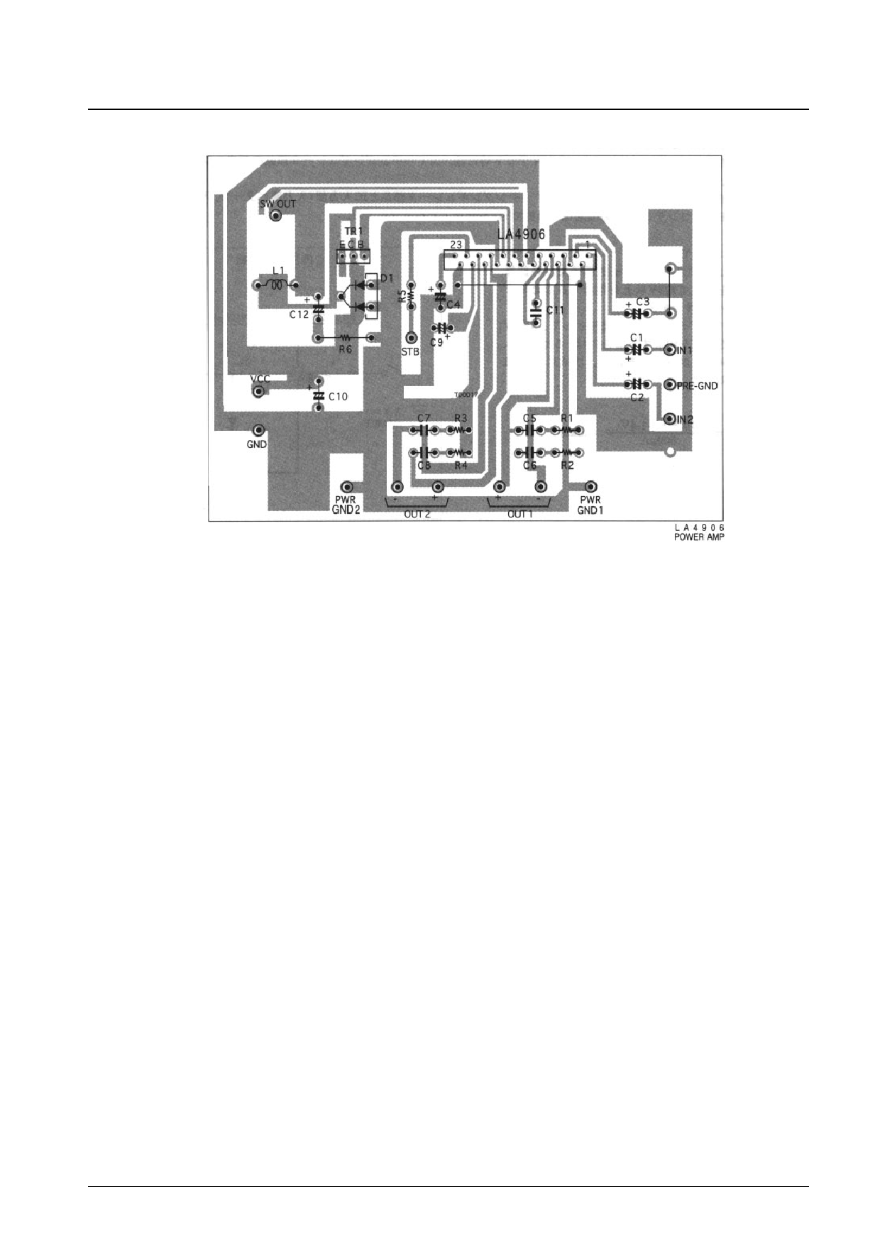
Sample Printed Circuit Board
LA4906
1. External component descriptions
C1 and C2
· Input capacitors. A value of 2.2 µF is recommended for these capacitors. Note that the low-frequency area
characteristics can be adjusted by changing fL, which is determined by the values of C1 and C2. However, due to
impulse (pop) noise considerations, the value of C1 and C2 should not exceed 3.3 µF when C4 is 22 µF.
C3
· Beep amplifier input capacitor. A value the same as that of C1 and C2 is used. If the beep function is not used, connect
the beep input to PRE-GND through C3.
C4
· Set the amplifier turn-on time. A value of 22 µF is recommended. (This will result in a turn-on time of about 0.7
second.) The on time is proportional to the value of this capacitor, and any value may be used. However, due to
impulse (pop) noise considerations, a value of 22 µF or larger should be used.
C5, C6, C7, and C8
· Oscillation prevention capacitors. Polyester film (Mylar) capacitors with good temperature characteristics must be used.
(These are used together with R1, R2, R3, and R4.) We recommend values of 0.1 µF or higher for these capacitors
since the stability will differ somewhat depending on the printed circuit board layout actually used.
C9
· Decoupling capacitor (ripple filter)
C10
· Power-supply capacitor
C11
· Oscillation prevention capacitor for the switching regulator. A value of 1500 pF is recommended.
C12
· Switching regulator output smoothing capacitor. The LA4906 adopts a self-excited switching regulator technique. The
value of this capacitor must be optimized, since it influences both the self-excitation stability and the regulator
efficiency. We recommend using a 2.2-µF 25-V OS (Organic Semiconductor) capacitor with a low series resistance
and good temperature characteristics. Note that for the same reason a 2.2-Ω 1/2-W resistor should be used for the
associated resistor R6.
R5
· Standby switch current limiter resistor. A value of 10 kΩ is recommended. (When the voltage applied to the standby
switch is in the range 3 to 13.2 V.) Note that this resistor cannot be removed from this circuit.
No. 5714-5/10
Share Link: 