DIM400DCM17-A000 Ver la hoja de datos (PDF) - Dynex Semiconductor
Número de pieza
componentes Descripción
Fabricante
DIM400DCM17-A000 Datasheet PDF : 8 Pages
| |||
DIM400DCM17-A000
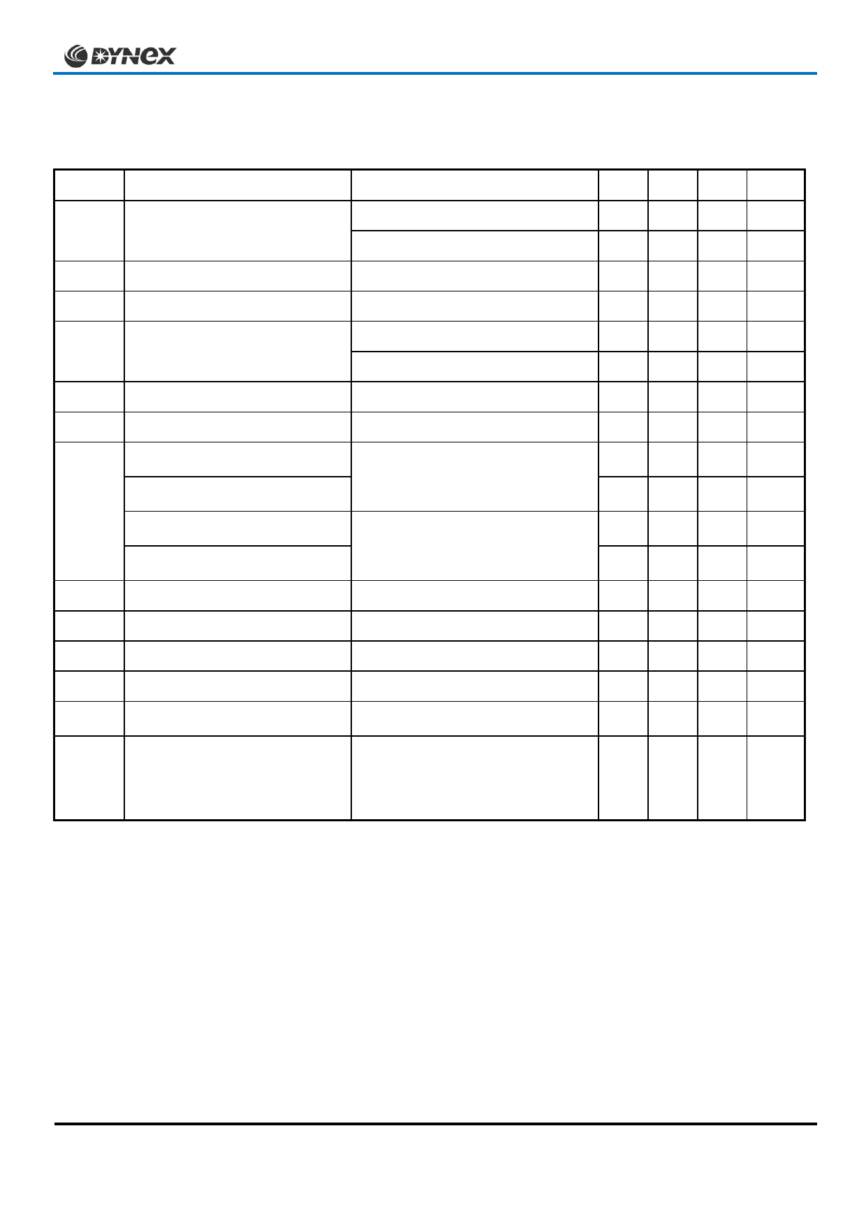
ELECTRICAL CHARACTERISTICS
Tcase = 25°C unless stated otherwise.
Symbol
Parameter
Test Conditions
ICES
IGES
VGE(TH)
VCE(sat) †
IF
IFM
VF †
Cies
Qg
Cres
LM
RINT
SCData
Collector cut-off current
Gate leakage current
Gate threshold voltage
Collector-emitter saturation
voltage
Diode forward current
Diode maximum forward current
Diode forward voltage
(IGBT arm)
Diode forward voltage
(Diode arm)
Diode forward voltage
(IGBT arm)
Diode forward voltage
(Diode arm)
Input capacitance
Gate charge
Reverse transfer capacitance
Module inductance – per arm
Internal transistor resistance –
per arm
Short circuit current, ISC
VGE = 0V, VCE = VCES
VGE = 0V, VCE = VCES, Tcase = 125°C
VGE = ± 20V, VCE = 0V
IC = 20mA, VGE = VCE
VGE = 15V, IC = 400A
VGE = 15V, IC = 400A, Tj = 125°C
DC
tp = 1ms
IF = 400A
IF = 400A, Tj = 125°C
VCE = 25V, VGE = 0V, f = 1MHz
±15V
VCE = 25V, VGE = 0V, f = 1MHz
Tj = 125°C, VCC = 1000V
tp ≤ 10μs, VGE ≤ 15V
VCE (max) = VCES – L* x dI/dt
IEC 60747-9
Min Typ Max
1
12
2
4.5 5.5 6.5
2.7 3.2
3.4 4.0
400
800
2.2 2.5
1.8 2.1
2.3 2.6
1.8 2.1
30
4.5
2.5
20
270
1600
Units
mA
mA
μA
V
V
V
A
A
V
V
V
V
nF
μC
nF
nH
μ
A
Note:
† Measured at the power busbars, not the auxiliary terminals
* L is the circuit inductance + LM
Caution: This device is sensitive to electrostatic discharge. Users should follow ESD handling procedures
3/8
www.dynexsemi.com
Share Link: 