DIM400DCM17-A000(2002) Ver la hoja de datos (PDF) - Dynex Semiconductor
Número de pieza
componentes Descripción
Fabricante
DIM400DCM17-A000 Datasheet PDF : 11 Pages
| |||
DIM400DCM17-A000
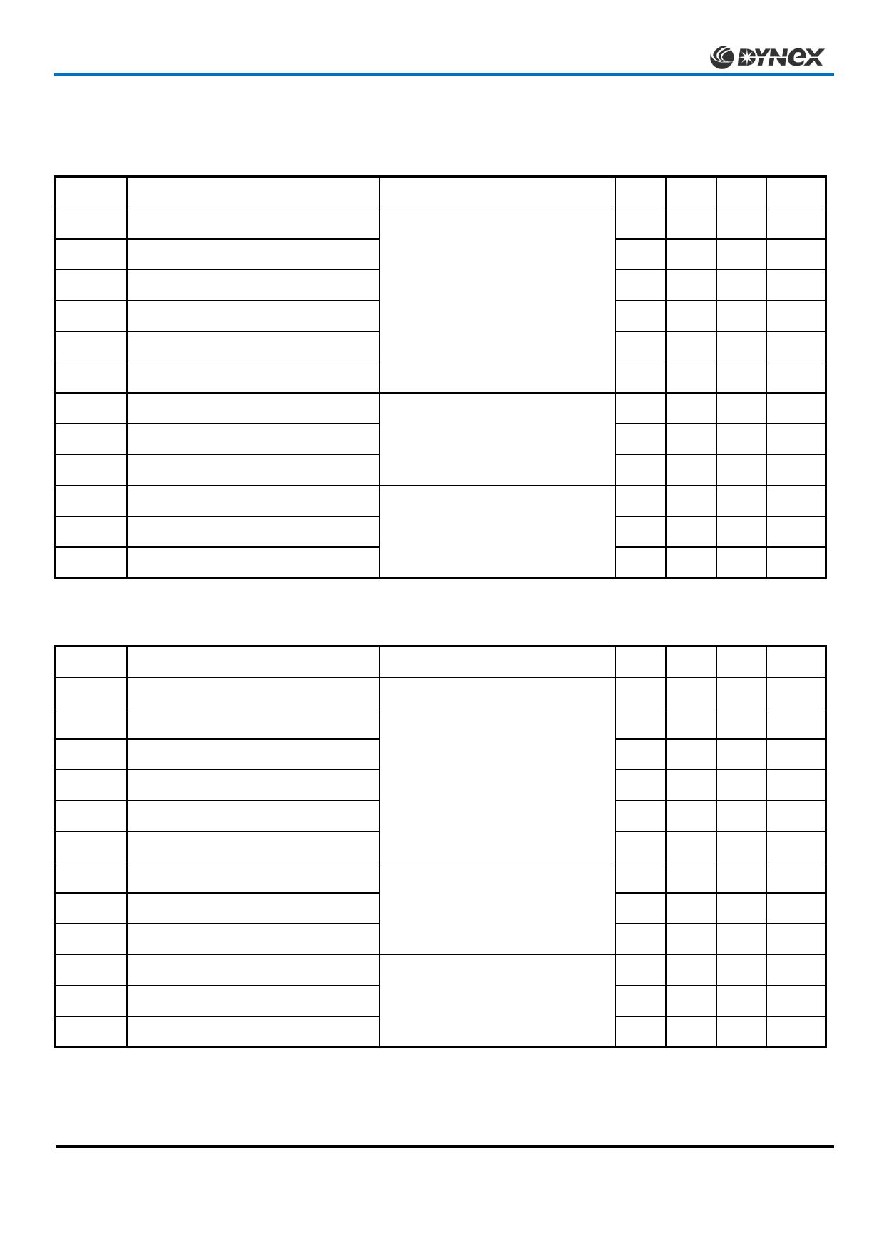
ELECTRICAL CHARACTERISTICS
Tcase = 25˚C unless stated otherwise.
Symbol
Parameter
Test Conditions
I
Collector cut-off current
CES
IGES
VGE(TH)
V†
CE(sat)
Gate leakage current
Gate threshold voltage
Collector-emitter saturation voltage
IF
Diode forward current
IFM
Diode maximum forward current
VF†
Diode forward voltage (IGBT arm)
Diode forward voltage (Diode arm)
V = 0V, V = V
GE
CE
CES
VGE = 0V, VCE = VCES, Tcase = 125˚C
VGE = ±20V, VCE = 0V
I = 20mA, V = V
C
GE
CE
VGE = 15V, IC = 400A
VGE = 15V, IC = 400A, , Tcase = 125˚C
DC
t = 1ms
p
IF = 400A
Diode forward voltage (IGBT arm)
Diode forward voltage (Diode arm)
IF = 400A, Tcase = 125˚C
Cies
Input capacitance
Cres
Reverse transfer capacitance
VCE = 25V, VGE = 0V, f = 1MHz
VCE = 25V, VGE = 0V, f = 1MHz
LM
RINT
SC
Data
Module inductance - per arm
Internal transistor resistance - per arm
Short circuit. ISC
-
-
Tj = 125˚C, VCC = 1000V,
I1
tp ≤ 10µs, VCE(max) = VCES – L*. di/dt I2
IEC 60747-9
Note:
† Measured at the power busbars and not the auxiliary terminals)
* L is the circuit inductance + LM
Min. Typ. Max. Units
-
-
1
mA
-
-
12 mA
-
-
2
µA
4.5
5.5
6.5
V
-
2.7
3.2
V
-
3.4
4.0
V
-
-
400 A
-
-
800 A
-
2.2
2.5
V
-
1.8
2.1
V
-
2.3
2.6
V
-
1.8
2.1
V
-
30
-
nF
-
2.5
-
nF
-
20
-
nH
-
0.27
-
mΩ
-
1850
-
A
-
1600
-
A
4/11
Caution: This device is sensitive to electrostatic discharge. Users should follow ESD handling procedures.
www.dynexsemi.com
Share Link: 