IL2410 Ver la hoja de datos (PDF) - Integral Corp.
Número de pieza
componentes Descripción
Fabricante
IL2410 Datasheet PDF : 7 Pages
| |||
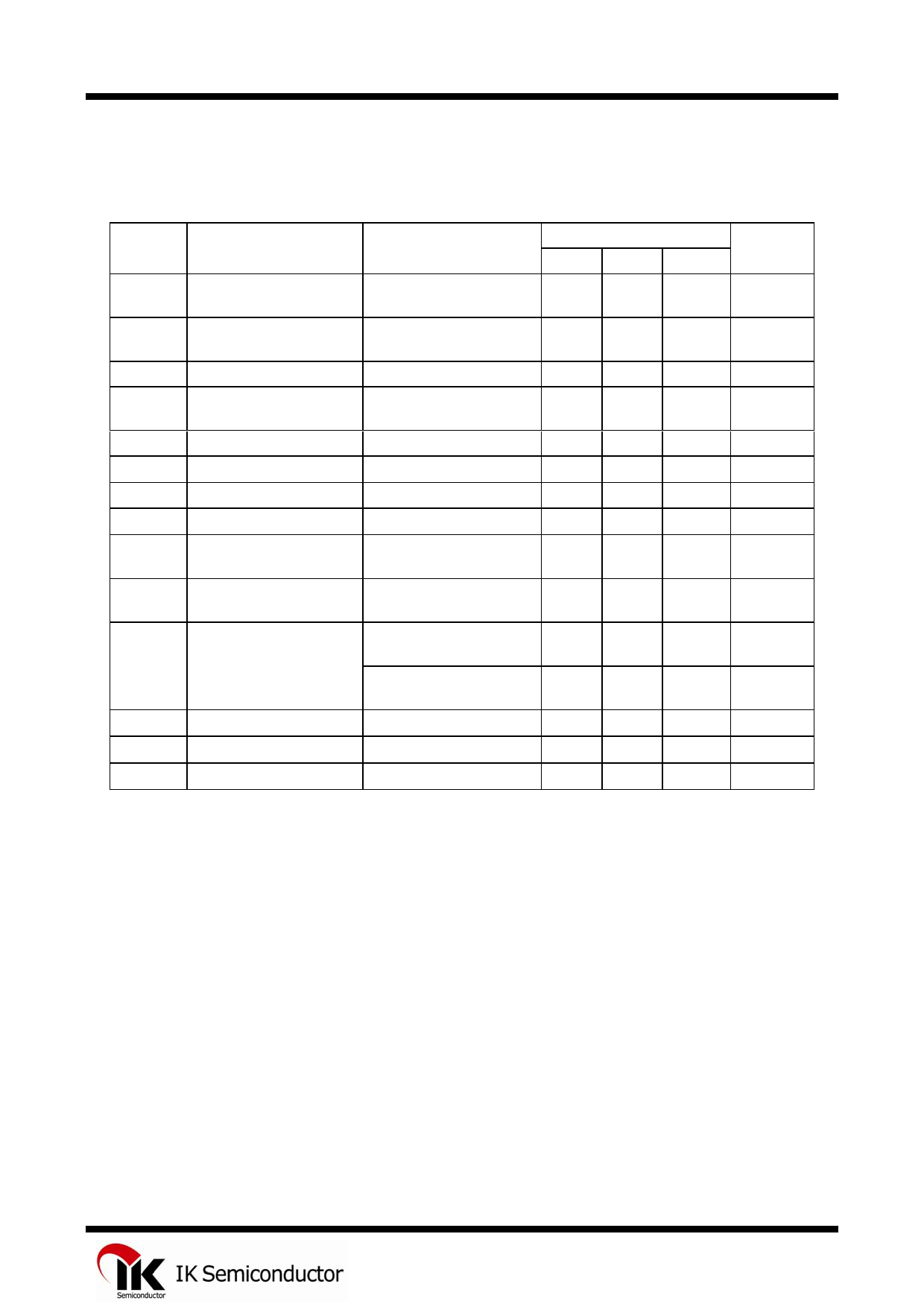
IL2410
ELECTRICAL CHARACTERISTICS (Voltages Referenced to GND, TA = -45 to +65°C)
Guaranteed Limits
Symbol
Parameter
Test Conditions
Min Typ Max
Unit
VSI Initiation Supply Voltage See Fig. 1
(1)
16.8
21.2
V
ISI
Initiation Supply Current
(1)
1.4
4.2
mA
VSUS Sustaining Voltage (2) See Fig. 1
9.5
12.2
V
ISUS
Sustaining Current (2)
No Load VCC=VSUS
0.7
See Fig. 1
2.5
mA
VTR Trigger Voltage (3)
VCC=15V
8.8
12.2
V
ITR Trigger Current (3,5)
VCC=15V
5.0
1000
µA
VDIS Disable Voltage (4)
VCC=21V
-
0.7
V
IDIS Disable Current (4)
VCC=15V
-20
-
µA
VOH High-Level Output
Voltage
VCC=21V, IOH=-15mA,
16.7
Pin 6=6V, Pin 7=GND
21.0
V
VOL Low-Level Output
VCC=21V, IOL=15mA,
-
Voltage
Pin 6=GND, Pin 7=6V
1.8
V
IIN
Maximun Input Leakage Pin 3=6V,
-
Current
(Pin 3) Pin 4=GND, VCC=21V
1.0
µA
(Pin 7) Pin 7=6V,
-
Pin 6=GND, VCC=21V
1.0
µA
fH1
High Frequency 1
R3=191KΩ,C3=6800pF
461
563
Hz
fH2
High Frequency 2
fL
Low Frequency
R3=191KΩ,C3=6800pF
576
R2=165KΩ, C2=0.47µF
9.0
704
Hz
11.0
Hz
Notes:
1. Initiation supply voltage (VSI) is the supply voltage required to start the tone ringer oscillating.
2. Sustaining voltage (VSUS) is the supply voltage required to maintain oscillation.
3. VTR and ITR are the conditions applied to trigger in to start oscillation for VSUS≤VCC≤VSI.
4. VDIS and IDIS are the conditions applied to trigger in to inhibit oscillation for VSI≤VCC.
5. Trigger current must be limited to this value externally.
3
Share Link: 