HT2040A Ver la hoja de datos (PDF) - Holtek Semiconductor
Número de pieza
componentes Descripción
Fabricante
HT2040A Datasheet PDF : 9 Pages
| |||
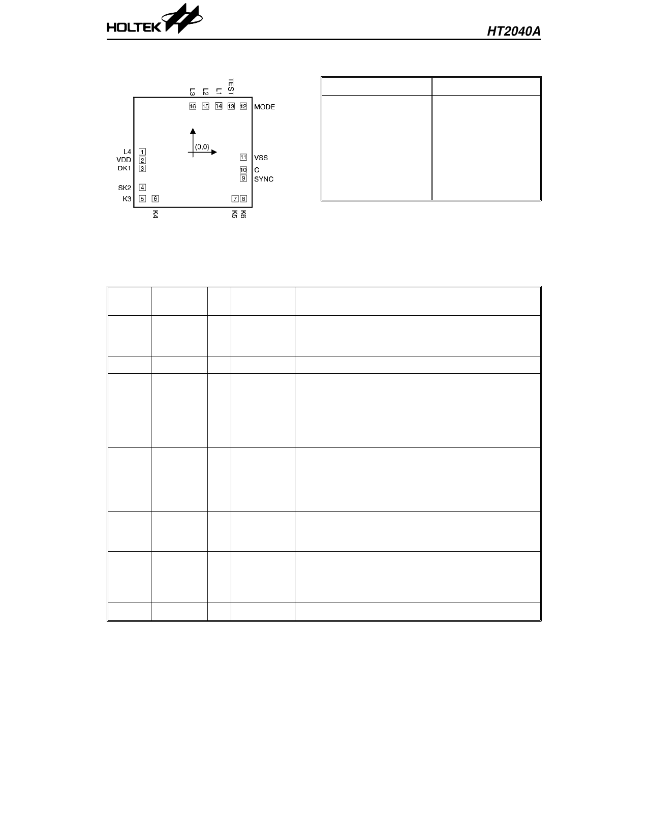
Pad Coordinates
HT2040A
Unit: mil
Pad No. X
Y Pad No. X
Y
1 –46.47 –0.17 9 46.47 –23.89
2 –46.47 –7.01 10 46.47 –16.24
3 –46.47 –14.66 11 46.47 –4.51
4 –46.47 –32.22 12 46.47 42.59
5 –46.47 –42.59 13 35.17 42.59
6 –34.74 –42.59 14 23.86 42.59
7 38.82 –42.59 15 11.62 42.59
8 46.47 –42.59 16 –0.32 42.59
Chip size: 107 × 99 (mil)2
* The IC substrate should be connected to VDD in the PCB layout artwork.
Pad Description
Pad No. Pad Name
I/O
Internal
Connection
Description
1
L4
Lamp driving signal
O
CMOS L4 generates a high SCR trigger signal to control the
lamp intensity.
2
VDD
I
—
Power supply (positive)
Demo function or group-5 selection input
If MODE is connected to VSS or open, DK1 will enable
3
DK1
I
CMOS the demo mode, i.e., show all the configurations (group-
Pull-Low 1 ~ group-10) by being momentarily connected to VDD.
If MODE is connected to VDD, group-5 will be shown by
connecting DK1 to VDD.
One key activated display or group-6 selection
4
SK2
I
CMOS
Pull-Low
If MODE is connected to VSS or floating, SK2 will
display the next group by being momentarily pressed.
If MODE is connected to VDD, group-6 will be shown by
connecting SK2 to VDD.
5~8
K3~K6
I
CMOS
Pull-Low
Group1 ~ Group4 selection
If MODE is connected to VSS or floating, group-7~
group-10 will be shown by connecting MODE to VDD.
PLL synchronous signal input
9
SYNC
I
CMOS
The PLL circuit is synchronized to the AC power
supply. The system can operate with a 60Hz or 50Hz
AC power supply system.
10
C
I
NMOS For low pass PLL filters
2
26th Mar ’97
Share Link: 