M24164-MN Ver la hoja de datos (PDF) - STMicroelectronics
NГәmero de pieza
componentes DescripciГіn
Fabricante
M24164-MN
STMicroelectronics

M24164-MN Datasheet PDF : 21 Pages
| |||
M24164
SUMMARY DESCRIPTION
The M24164 is a 16 Kbit (2048 x 8) electrically
erasable programmable memory (EEPROM) ac-
cessed by an I2C-compatible bus.
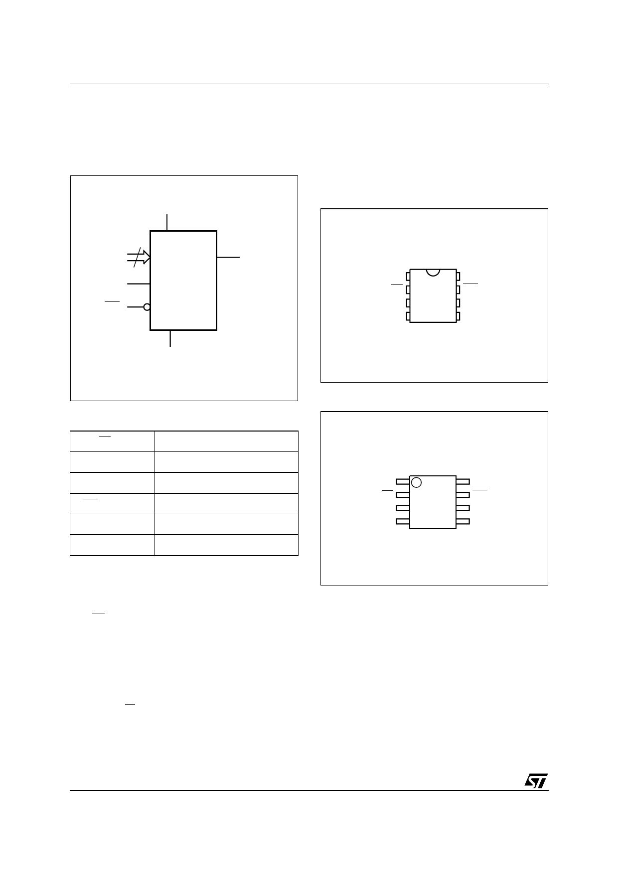
Figure 2. Logic Diagram
VCC
following the bus masterвҖҷs 8-bit transmission.
When data is read by the bus master, the bus
master acknowledges the receipt of the data byte
in the same way. Data transfers are terminated by
a Stop condition after an Ack for Write, and after a
NoAck for Read.
Figure 3. DIP Connections
3
E0-E2
SCL
WC
M24164
SDA
VSS
AI02264
M24164
E0 1
E1 2
8 VCC
7 WC
E2 3
6 SCL
VSS 4
5 SDA
AI02265B
Table 1. Signal Names
E0, E1, E2
Chip Enable
SDA
Serial Data
SCL
Serial Clock
WC
Write Control
VCC
VSS
Supply Voltage
Ground
Figure 4. SO Connections
E0
E1
E2
VSS
M24164
1
8
2
7
3
6
4
5
AI02266B
VCC
WC
SCL
SDA
These devices are compatible with a two-wire se-
rial interface that uses a bi-directional data bus
and serial clock. By setting the three chip enables
(E0, E1, E2) appropriately, up to eight 16 Kbit de-
vices can be attached to the same I2C bus, and
selected individually.
These devices behave as slave devices, with all
memory operations synchronized by the serial
clock. Read and Write operations are initiated by a
Start condition, generated by the bus master. The
Start condition is followed by a Device Select
Code and RW bit (as described in Table 2), termi-
nated by an acknowledge bit.
When writing data to the memory, the device in-
serts an acknowledge bit during the 9th bit time,
Power On Reset: VCC Lock-Out Write Protect
In order to prevent data corruption and inadvertent
Write operations during Power-up, a Power On
Reset (POR) circuit is included. The internal reset
is held active until VCC has reached the POR
threshold value, and all operations are disabled вҖ“
the device will not respond to any command. In the
same way, when VCC drops from the operating
voltage, below the POR threshold value, all oper-
ations are disabled and the device will not respond
to any command. A stable and valid VCC must be
applied before applying any logic signal.
2/21
Share Link: