UB2 Ver la hoja de datos (PDF) - GREATECS
Número de pieza
componentes Descripción
Fabricante
UB2 Datasheet PDF : 2 Pages
| |||
Illuminated Switches
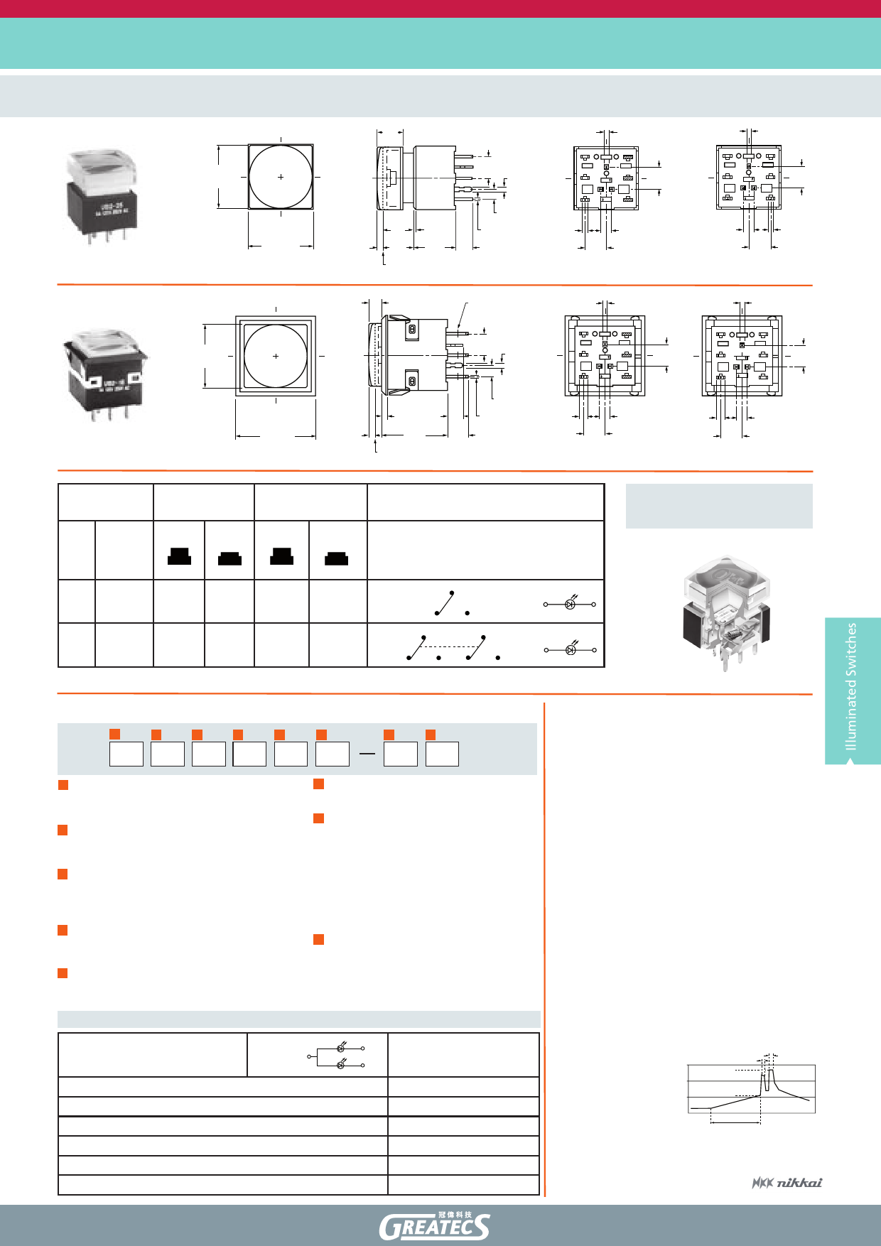
Bicolor illuminated Pushbutton Switches with Alternating Legends
UB2 Series
(6.1)
.240
(15.0) Sq
.591
(5.08) Typ
.200 (1.0)
.039
UB225SKW036CF-4J01
(15.24) Sq
.600
(1.5)
.059
(0.5)
.020
(7.0) (10.0) (4.0)
.276 .394 .157
Latchdown Position
Bicolor LED Straight PC
(2.54) Typ
.100
(0.5) Typ
.020
(3.0)
(0.8) x (1.6) Typ
.118
.032 x .063
(15.0) Sq
.591
(5.08) Typ
.200 (1.0)
.039
UB216KKW016CF-4J02
(1.4)
(4.0)
.055
.157
(19.0) Sq
.748
(1.5)
(15.5)
(5.0)
.059
.610
.197
Latchdown Position
Bicolor LED Solder Lug
(2.54) Typ
.100
(0.5) Typ
.020
(1.0)
.039
3
N.C.
2
N.O.
1 COM
LC
N.C.
L2
N.O.
COM
L1
(5.08)
.200
(1.0)
.039
(2.54)
.100
(5.08)
.200
Single Pole
(1.0)
.039
3
N.C.
2
N.O.
1 COM
LC
N.C.
L2
N.O.
COM
L1
(5.08)
.200
(1.0)
.039
3
N.C.
2
N.O.
1 COM
6
LC
N.C.
5
L2
N.O.
COM 4
L1
(5.08)
.200
(2.54)
.100
(1.0) Typ
.039
(5.08) Typ
.200
Double Pole
(1.0)
.039
3
N.C.
2
N.O.
1 COM
6
LC
N.C.
5
L2
N.O.
L 1 COM 4
(5.08)
.200
(2.0)
(2.54)
.079
.100
(5.08)
.200
Single Pole
(2.0) Typ
.079
(2.54)
.100
(5.08)
.200
Double Pole
POLE &
CIRCUITS
Pole Model
Plunger Position Connected Terminals
Throw & Switch/Lamp Schematics
Normal Down Normal
Down
Notes: Switch is marked with NC, NO, COM, L+
& L-. Lamp circuit is isolated and requires an
external power source.
CUTAWAY
SP
UB215
UB216*
ON
ON
(ON)
ON
1-3
1-2
SPDT
1 COM
3 NC 2 NO
(+)
(-)
DP
UB225
UB226*
ON
ON
(ON)
ON
1-3 4-6
1-2 4-5
1 COM
4 COM
DPDT 3 NC 2 NO 6 NC 5 NO
(+)
(-)
When in latchdown position for the alternate circuit, cap positions above the housing are: 1.5mm for snap-in models & 7.0mm for PCB models.
How to order:
General Specifications:
1
2
3
4
5
6
UB2
7
8
1 POLES:
6 LED:
1 SPDT
6CF red/green Super Bright Bicolor LED
2 DPDT
7 CAP TYPES & COLORS:
2 CIRCUITS:
1JB Sculptured Cap: Clear
5 ON-(ON)
Diffuser Color: White
6
ON-ON (Alternate Action with Latchdown)
2B Beveled Cap & Color: White
3JB Flat Cap Lens: Clear
3 MOUNTING TYPES:
Diffuser Color: White
SK Square (PCB Mounting)
4J Sculptured Cap with Alternating
KK Square (Snap-in Mounting, Standard
Legend Filter: Clear Lens
with Solder Lug terminals)
5J Flat Cap with Alternating Legend
Filter: Clear Lens
4 CONTACTS & RATINGS:
W Silver Rated 5A @ 125/250 VAC
8 ALTERNATING LEGENDS:
G Gold Rated 0.4VA max @ 28V AC/DC max 01 ON/OFF
02 START/STOP
5 TERMINALS:
04 OPEN/CLOSE
01 Solder Lug (for Snap-in Mounting)
02 Straight PC
LED COLORS & SPECIFICATIONS
The electrical specifications shown are determined
at a basic temperature of 25°C. Amber can be
achieved by simultaneous illumination of red &
green, but is not suitable for Alternating Legends.
Bicolor
with 2 LC (+)
elements
Forward Peak Current
IFM
Continuous Forward Current
IF
Forward Voltage
VF
Reverse Peak Voltage
VRM
Current Reduction Rate Above 25°C ∆IF
Ambient Temperature Range
L1 (-)
6CF
Red
Super Bright Bicolror
L2 (-)
Green
Red/Green
30/25(25/22 for Amber) mA
20/20 mA
2.1/3.5 V
4/4 V
0.40/0.33 mA/°C
-25°C ~ +50°C
ELECTRICAL CAPACITY (Resistive Load)
» Power Level (code W): 5A@125/250VAC or 5A@30VDC
» Logic Level (code G): 0.4VA max.@28V AC/DC max.
(Applicable Range 0.1mA~0.1A@20mV~28V)
OTHER RATINGS:
» Contact Resistance: 50mΩ max. for silver; 100mΩ max. for gold
» Insulation Resistance: 200MΩ min.@500VDC
» Mechanical Life: 1,000,000 operations min. for momentary;
200,000 operations for alternate action
» Electrical Life: 10,000 operations min. for silver;
200,000 operations min. for gold
» Norminal Operating Force: SP: 1.90N; DP: 2.55N
» Contact Timing: Break-before-make
» Travel: Pretravel: 1.7mm; Overtravel: 0.6mm; Total: 2.3mm
MATERIALS
» Movable Contacts & Stationary Contacts:
Silver alloy or copper with gold plating
» Switch Terminals: Phosphor bronze with silver or gold plating
» Lamp Terminals: Brass with silver plating
ENVIRONMENTAL DATA
» Operating Temperature: -25°C through +50°C
SOLDERING
» Manual Soldering: 4 seconds max. @ 410°C max.
» Wave Soldering (PC version):
t3
t2
See Profile:
T2
T1
0
t1
t = seconds
Pro le A
Depending on the material and thickness of the PCB, surface
temperatures may vary. If the process exceeds the wave soldering
limits in this graph, contact us for further information.
sales@greatecs.com
www.greatecs.com
Share Link: 