SS559(2012) Ver la hoja de datos (PDF) - SEC Electronics Inc.
Número de pieza
componentes Descripción
Fabricante
SS559 Datasheet PDF : 8 Pages
| |||
SS559
Hall Latch - High Sensitivity
Application Information
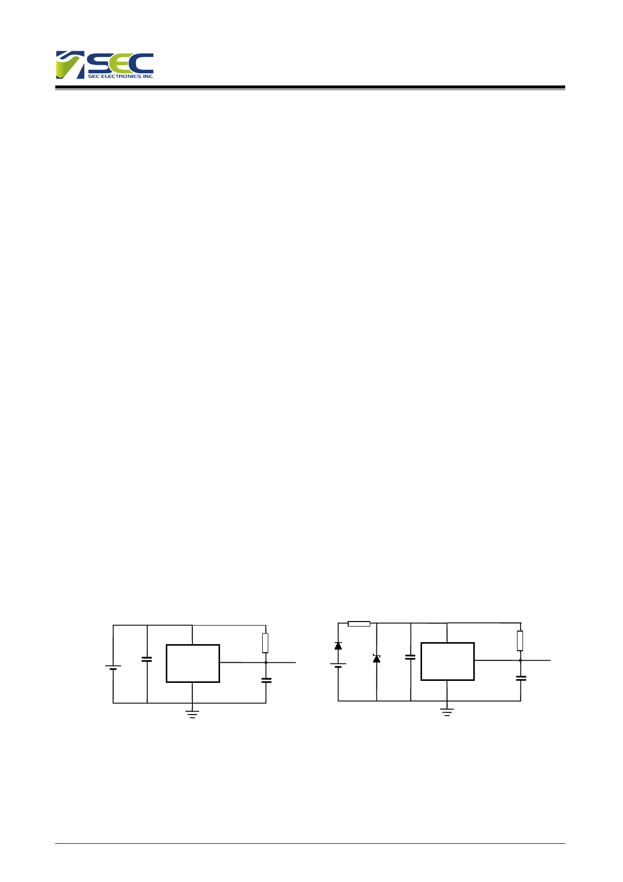
It is strongly recommended that an external bypass capacitor be connected (in close proximity to the Hall sensor)
between the supply (VDD Pin) and ground (GND Pin) of the device to reduce both external noise and noise generated
by the chopper stabilization technique. As is shown in the two figures in next page, a 0.1μF capacitor is typical.
For reverse voltage protection, it is recommended to connect a resistor or a diode in series with the VDD pin. When
using a resistor, three points are important:
- the resistor has to limit the reverse current to 50mA maximum (VCC / R1 ≤ 50mA)
- the resulting device supply voltage VDD has to be higher than VDD min (VDD = VCC – R1*IDD)
- the resistor has to withstand the power dissipated in reverse voltage condition (PD = VCC2/R1)
When using a diode, a reverse current cannot flow and the voltage drop is almost constant (≈0.7V).
Therefore, a 100Ω/0.25W resistor for 5V application and a diode for higher supply voltage are recommended. Both
solutions provide the required reverse voltage protection.
When a weak power supply is used or when the device is intended to be used in noisy environment, it is recommended
The figure 13.3 from the Application Information section is used.
The low-pass filter formed by R1 and C1 and the zener diode Z1 bypass the disturbances or voltage spikes occurring
on the device supply voltage VDD. The diode D1 provides additional reverse voltage protection.
Typical Three-Wire Application Circuit
C1
VDD
R2
OUT
SS559
C2
GND
Automotive and Severe
Environment Protection Circuit
R1:100
C1
VDD
R2
D1
Z1
SS559 OUT
C2
GND
The SS559 have been optimized for commutation applications in 5V and 12V brushless DC motors. The follow figure
is the typical application circuit for 3 phase brushless DC motors.
5
V2.10 May 1, 2012
Share Link: 