SAA1101 Ver la hoja de datos (PDF) - Philips Electronics
Número de pieza
componentes Descripción
Fabricante
SAA1101 Datasheet PDF : 18 Pages
| |||
Philips Semiconductors
Universal sync generator (USG)
Product specification
SAA1101
fpage
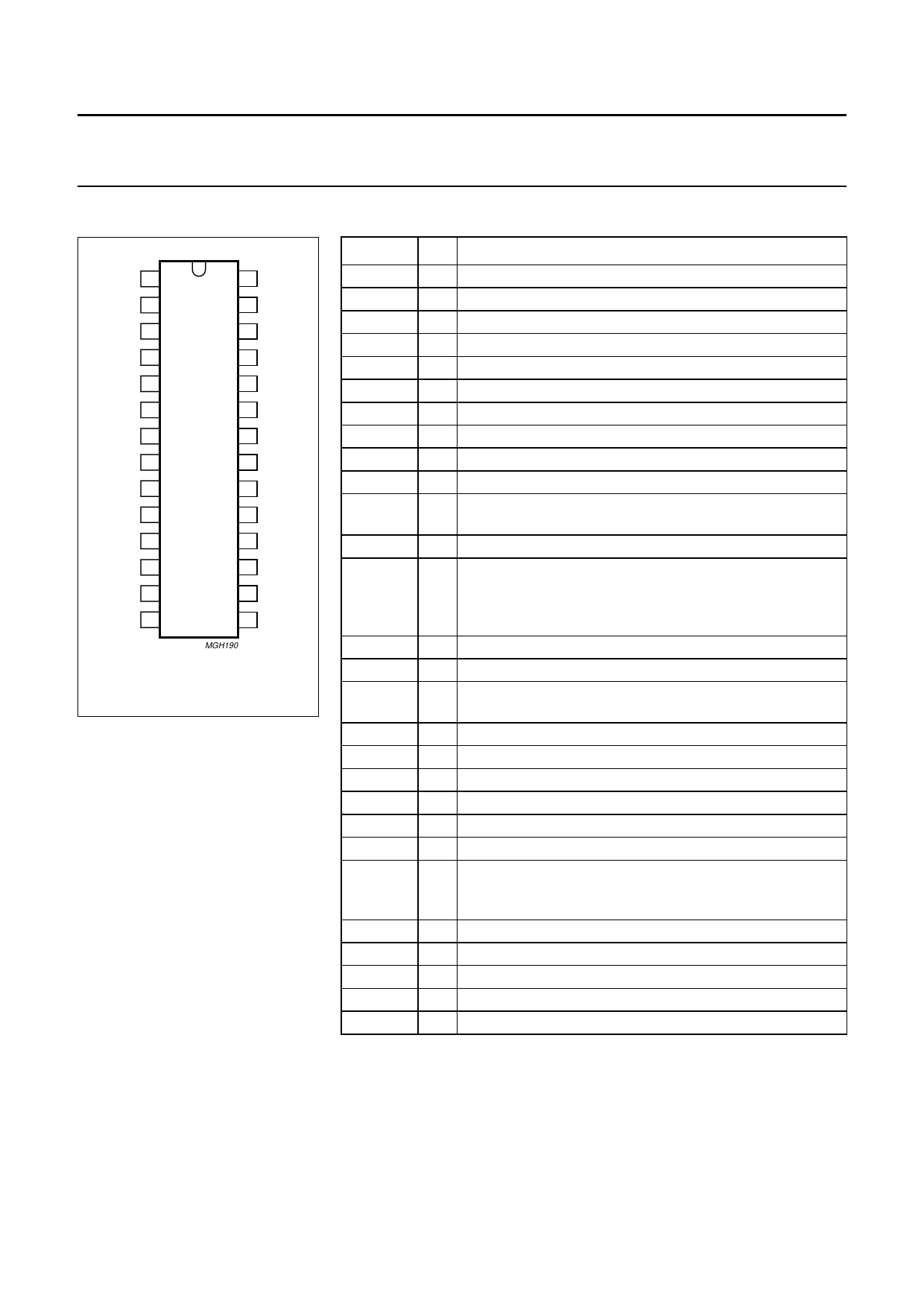
FSI 1
FSO 2
28 VDD
27 Z
CS1 3
26 Y
CS0 4
25 X
OSCI 5
24 CLO
OSCO 6
23 NORM
VLE 7
PH 8
22 HD
SAA1101
21 VD
LM1 9
20 WMP
LM0 10
19 CLP
ECS 11
18 CS
RR 12
17 CB
SI 13
16 BK
VSS 14
15 ID
MGH190
Fig.2 Pinning configuration;
SOT117.
FUNCTIONAL DESCRIPTION
Generation of pulses
Generation of standard pulses such
as sync, blanking and burst for TV
systems: PAL B/G, PALN, PALM,
SECAM and NTSC. In addition a
number of non-standard pulses have
been supplied to simplify signal
processing. These signals include -
horizontal drive, vertical drive, clamp
pulse, identification etc. It is possible
to select the 524/624 line mode
instead of the 525/625 line mode for
all the above TV systems for
applications such as robotics, games
and computers.
PINNING
SYMBOL PIN
DESCRIPTION
FSI
FSO
1 subcarrier oscillator input, where fmax = 5 MHz
2 subcarrier oscillator output
CS1
3 clock frequency selection - CMOS input
CS0
4 clock frequency selection - CMOS input
OSCI
5 clock oscillator input, where fmax = 24 MHz
OSCO 6 clock oscillator output
VLE
7 vertical in-lock enable - CMOS input
PH
8 phase detector output - 3-state output
LM1
9 lock mode selection - CMOS input
LM0
10 lock mode selection - CMOS input
ECS
11 external composite sync. signal - CMOS Schmitt-trigger
input
RR
12 frame reset - CMOS Schmitt-trigger input
SI
13 set identification, used to set the correct field sequence in
PAL-mode. The correction (inversion of fH2) is done at the
left-hand slope of the SI-pulse. Minimum pulse width is
800 ns. CMOS Schmitt-trigger input.
VSS
14 ground
ID
15 identification - push-pull output
BK
16 burst key (PAL/NTSC), chroma-blanking (SECAM) -
push-pull output
CB
17 composite blanking - push-pull output
CS
18 composite sync. - push-pull output
CLP
19 clamp pulse - push-pull output
WMP
20 white measurement pulse-3-state output
VD
21 vertical drive pulse - push-pull output
HD
22 horizontal drive pulse - push-pull output
NORM
23 used with X, Y and Z to select TV system; NORM = 0,
625/525 line mode (standard);
NORM = 1, 624/524 line mode - CMOS input
CLO
24 clock output - push-pull output
X
25 TV system selection input - CMOS input
Y
26 TV system selection input - CMOS input
Z
27 TV system selection input - CMOS input
VDD
28 voltage supply
January 1990
4
Share Link: 