HV857X Ver la hoja de datos (PDF) - Supertex Inc
Número de pieza
componentes Descripción
Fabricante
HV857X Datasheet PDF : 14 Pages
| |||
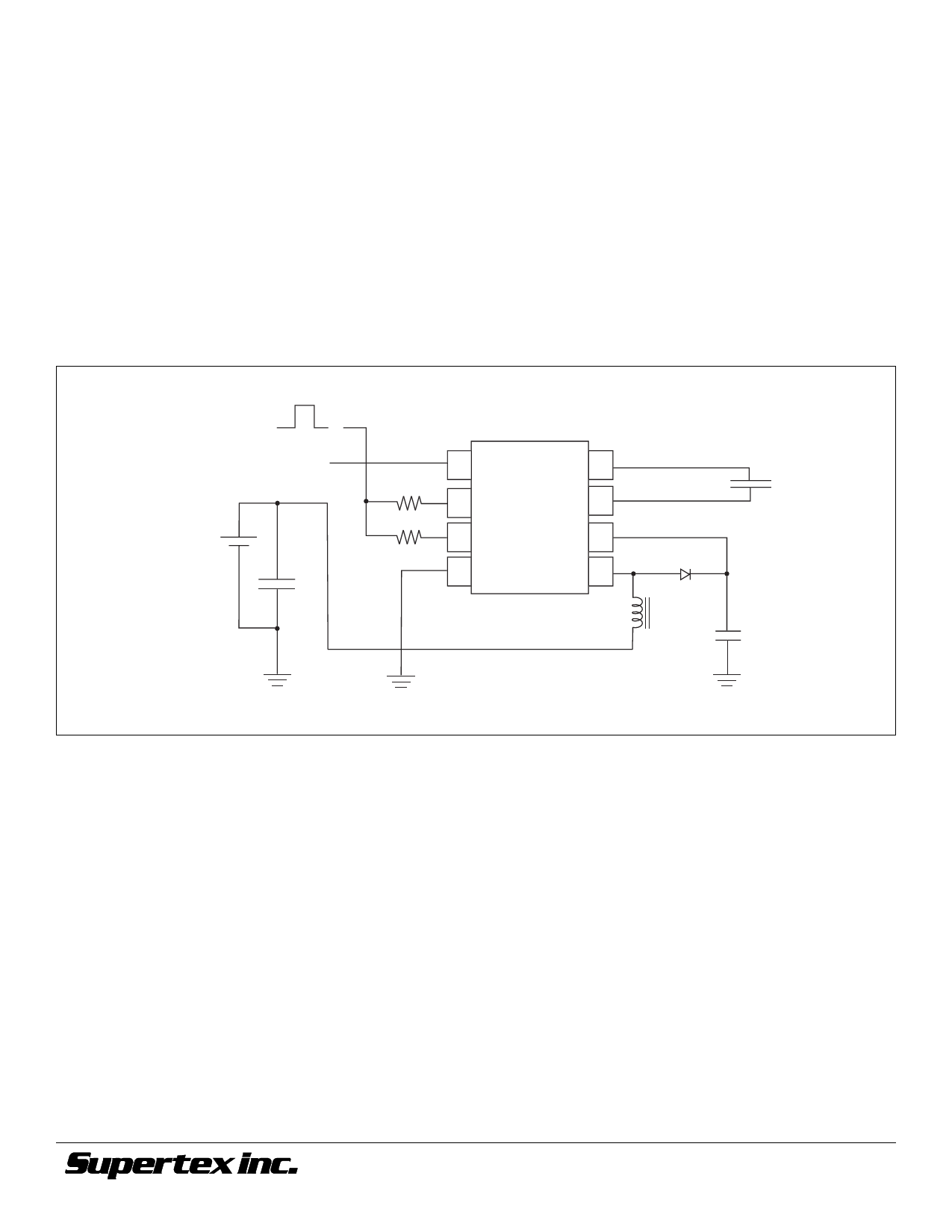
Split Supply Configuration
The HV857 can also be used for handheld devices operating
from a battery where a regulated voltage is available. This is
shown in Figure 2. The regulated voltage can be used to run
the internal logic of the HV857. The amount of current neces-
sary to run the internal logic is 150µA Max at a VDD of 3.0V.
Therefore, the regulated voltage could easily provide the
current without being loaded down.
HV857
Enable/Disable Configuration
The HV857 can be easily enabled and disabled via a logic control
signal on the RSW and REL resistors as shown in Figure 2 below.
The control signal can be from a microprocessor. RSW and REL
are typically very high values. Therefore, only 10’s of microam-
peres will be drawn from the logic signal when it is at a logic high
(enable) state. When the microprocessor signal is high the
device is enabled and when the signal is low, it is disabled.
Figure 2: Split Supply and Enable/Disable Configuration
ON=VDD
OFF=0
Enable Signal
Regulated Voltage=VDD
+
Battery Voltage=VIN_
CIN
1 VDD
VA 8
2 RSW-osc
VB 7
3 REL-osc
4 Gnd
CS 6
LX 5
HV857MG
LX
EL Lamp
CS
©2001 Supertex Inc. All rights reserved. Unauthorized use or reproduction prohibited.
6
11/14/01rev.10
1235 Bordeaux Drive, Sunnyvale, CA 94089
TEL: (408) 744-0100 • FAX: (408) 222-4895
www.supertex.com
Share Link: 