RF106 Ver la hoja de datos (PDF) - Conexant Systems
Número de pieza
componentes Descripción
Fabricante
RF106 Datasheet PDF : 6 Pages
| |||
RF106 900 MHz Power Amplifier
Specifications
Table 2 lists the absolute maximum ratings for the RF106.
Table 3 gives the electrical specifications for the RF106.
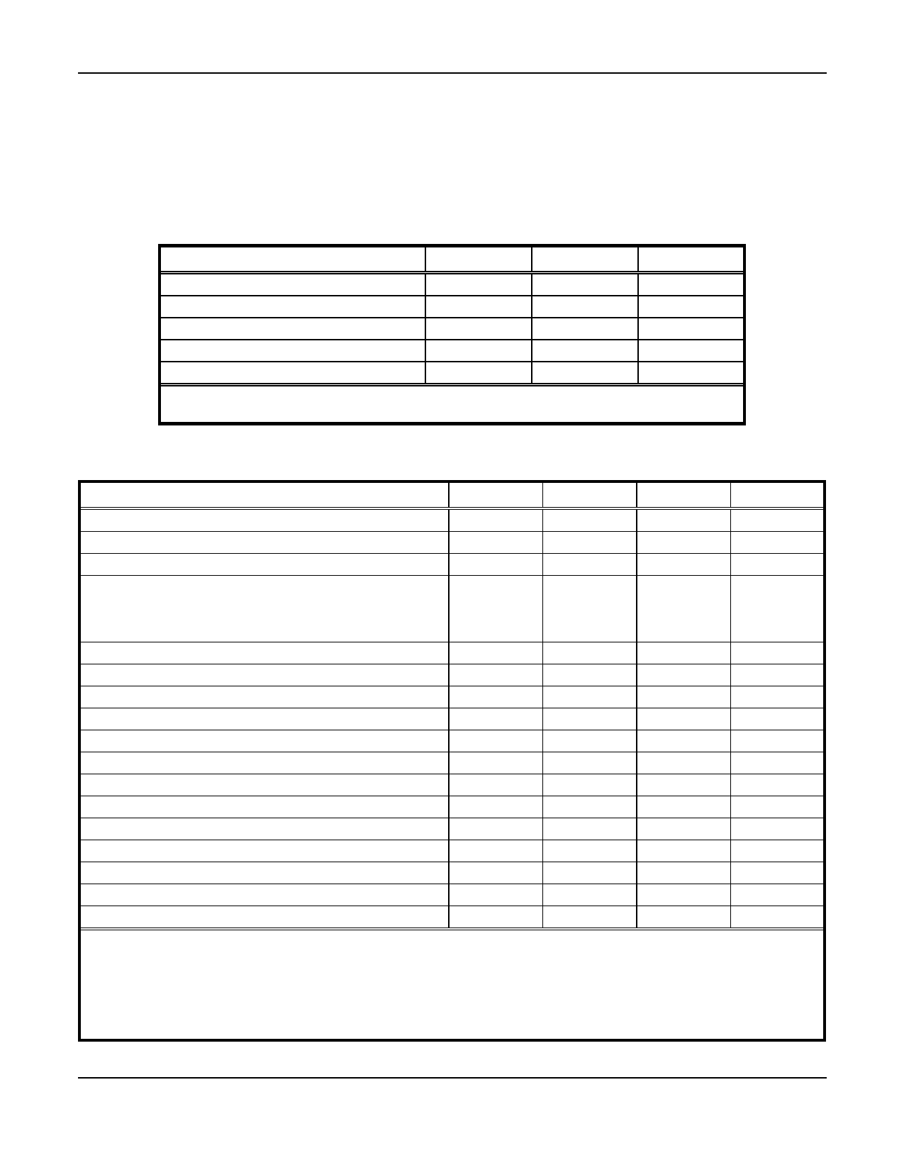
Table 2. Absolute Maximum Ratings
Parameter
Supply voltage (Vcc) (note 1)
Input voltage range (note 1)
Power dissipation @ high output power mode
Ambient operating temperature
Storage temperature
Notes:
1. Voltages are referenced to GND.
Min.
GND
–10
–40
Max.
+5
VCC
400
+70
+125
Unit
V
V
mW
°C
°C
Table 3. RF106 Electrical Specifications (note 1)
Parameter
Gain variation vs. frequency (902–928 MHz)
Peak-Envelope output Power (PEP) (note 2)
RF gain
Total supply current:
Output PEP = 21 dBm
Output PEP = 11 dBm
Output PEP = 1 dBm
Standby (note 5)
IM3: PEP ≤ 21 dBm
Output VSWR for unconditional stability
RF input return loss (902–928 MHz)
RF output-to-input isolation @ 915 MHz
RF input impedance
RFOUT passband 3dB BW around 915 MHz
VIH for ENABLE
VIL for ENABLE
IIH for ENABLE
IIL for ENABLE
Power supply for specified performance
Power supply range
Operating temperature range
Notes:
1. Test conditions: TA = 25 °C, VCC = 3.3V, fREF = 915 MHz
2. With continuous wave RF input signal of –8 dBm.
3. With continuous wave RF input signal of –18 dBm.
4. With continuous wave RF input signal of –28 dBm.
5. When ENABLE (pin 10) is low.
Min.
18
26
250
1.9
–10
3.0
2.7
–10
Typ.
±0.15
21
29
95 (note 2)
40 (note 3)
30 (note 4)
<1
–21
50
50
50
–1
3.6
3.6
25
Max.
±0.75
22
30
–17
10:1
–9.5
0.8
60
0
5.0
5.0
70
4
Conexant
Units
dB
dBm
dB
mA
mA
mA
µA
dBc
dB
dB
Ω
MHz
V
V
µA
µA
V
V
°C
W118
2/1/98
Share Link: 