PM9904BPD Ver la hoja de datos (PDF) - South African Micro Electronic Systems
Número de pieza
componentes Descripción
Fabricante
PM9904BPD Datasheet PDF : 22 Pages
| |||
PM9904BPD
THE MICRO-CONTROLLER BOARD
OVERVIEW
This section describes the plug-in micro-controller board and
should be read in conjunction with the evaluation software
section, where basic metering software is described. The
micro-controller’s software was developed according to this
section. The board plugs into the evaluation module as
described earlier in this application note.
1
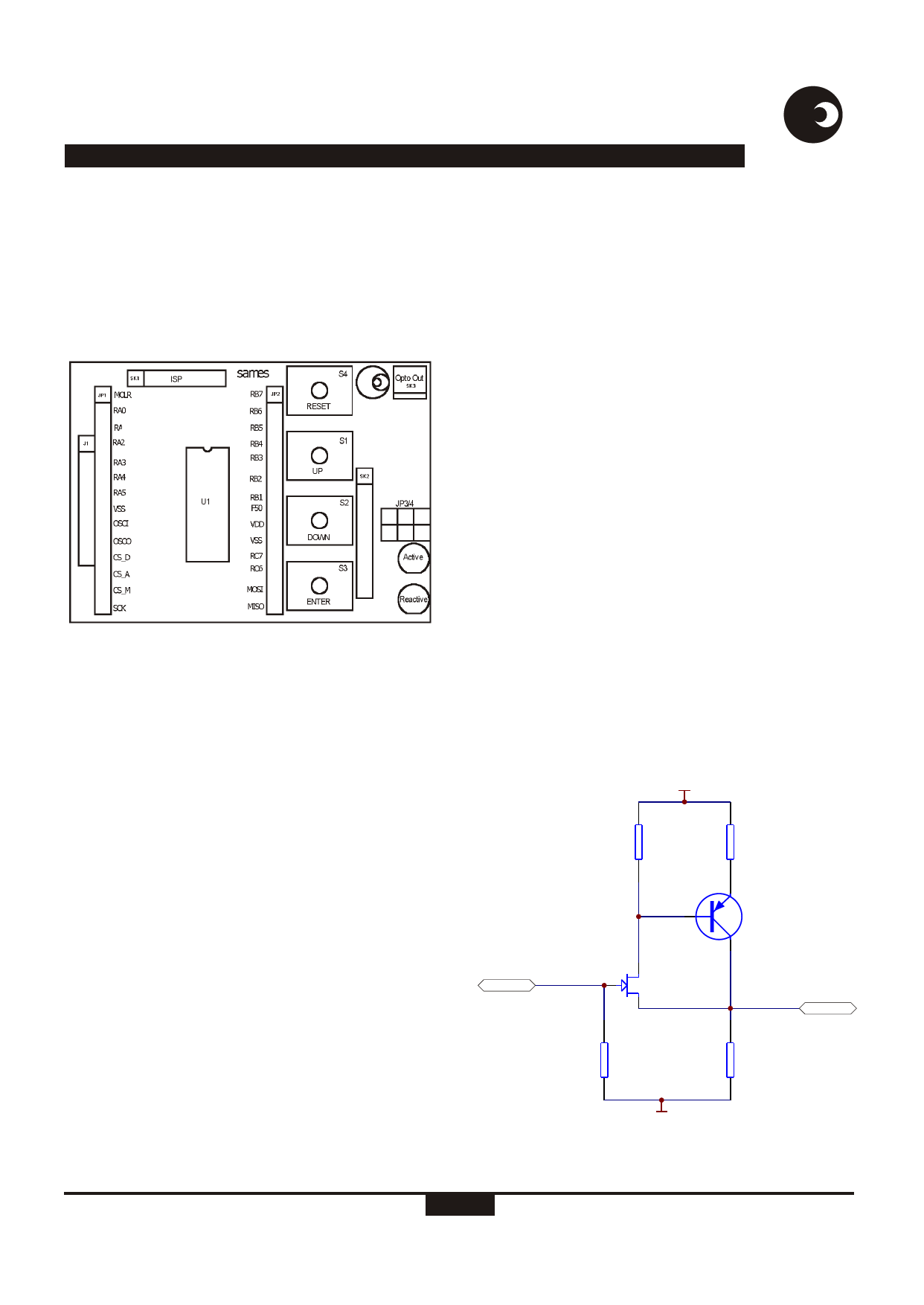
Figure 7: Micro-controller board
Hardware
The schematic is presented in Figure 18. As can be seen the
major elements are:
+ micro-controller,
+ eeprom,
+ keys,
+ rate LEDs / opto-isolated rate pulse output
+ and miscellaneous connectors.
Micro-controller
A PIC 16F876-20/so is used to generate the rate pulses, in this
application the micro uses a 20 MHz crystal (X1). This device
has 8kB Flash ROM (program memory) and 368 Byte RAM
(data memory). Detail information on the device can be
obtained in the appropriate MICROCHIP datasheet.
EEPROM
A 93C46 EEPROM provides storage for non-volatile data,
such as calibration factors. This device has 1 kB space
available or stated differently 128 x 8bit words.
sames
Keys
Four keys are provided of which one is connected to the micro-
controller’s reset pin. The other three are available to
implement an HMI (Human Machine Interface) in the firmware;
they’re labelled Up/Down and Enter on the printed circuit
board.
Rate outputs
Two LEDs are provided for active and re-active energy
respectively. These pulse outputs can be coupled to an opto-
coupler via JP3/4 providing an output for external usage. This
output-pulse selection is accomplished with a jumper on JP3/4
as follows:
+
Jumper on board’s outside edge = a ctive
+
Jumper on board’s centre pins
= re -active
+
Jumper on board’s inside edge
= not used
Miscellaneous
Connectors JP1 and JP2 are provided to ease debugging
during code development, all relevant signals are available. J1
in conjunction with SK2 are the two plug-in points to the
evaluation module, where SK2 is the SPI connector and J1
merely a stabilising holder. The micro-controller is
programmed via SK1 using the controller’s ICSP (in circuit
serial programming) capability, as described in the relevant
MICROCHIP datasheet. If the intention is to program the board
from MICROCHIP’s PICSTART-programmer a buffer needs to
be inserted in the VDD line to boost the programmer’s output
capability. An example of such a buffer is shown in Figure 8.
>5V
820K
R1
100R
R3
2N3906
I/P
2N3819
O/P
1.2M
R5
820K
R2
0V
Figure 8: Typical buffer circuit
http://www.sames.co.za
6/22
Share Link: 