M66503 Ver la hoja de datos (PDF) - MITSUBISHI ELECTRIC
Número de pieza
componentes Descripción
Fabricante
M66503 Datasheet PDF : 8 Pages
| |||
MITSUBISHI 〈DIGITAL ASSP〉
M66503ASP/AGP
16-BIT CONSTANT CURRENT LED DRIVER with SHIFT REGISTER AND LATCH
TIMING CONDITIONS (VCC=5V ± 10%, Ta=–20 ~ 85˚C)
Symbol
Parameter
tw
tsu(A)
tsu(LE)
th(A)
tr, tf
CKS, LE pulse width
Address setup time to CKS
LE setup time to CKS
Address hold time to CKS
CKS rise and fall time
Test conditions
(Note 6)
Limits
Unit
Min.
Typ.
Max.
30
ns
20
ns
40
ns
10
ns
2
µs
SWITCHING CHARACTERISTICS (VCC=5V ± 10%, Ta=–20 ~ 85˚C)
Symbol
Parameter
fmax
Maximum frequency for repetitions
tPLZ
“L-H” and “Z-L” outputs
CKS–Q0~15(off)
tPZL
propagation time
CKS–Q0~15(on)
tPLH
tPHL
“L-H” and “H-L” outputs
propagation time
CKS–SQ15
tPLZ
“L-Z” and “Z-L” outputs
LE–Q0~15(off)
tPZL
propagation time
LE–Q0~15(on)
tPLZ
“L-Z” and “Z-L” outputs
OEA–Q0~15(off)
tPZL
propagation time
OEA–Q0~15(on)
tPLZ
“L-Z” and “Z-L” outputs
OEB–Q0~15(off)
tPZL
propagation time
OEB–Q0~15(on)
Test conditions
CL=50pF
RL=100Ω
(Note 6)
Limits
Unit
Min.
Typ.
Max.
5
MHz
250
ns
250
ns
250
ns
250
ns
250
ns
250
ns
250
ns
250
ns
250
ns
250
ns
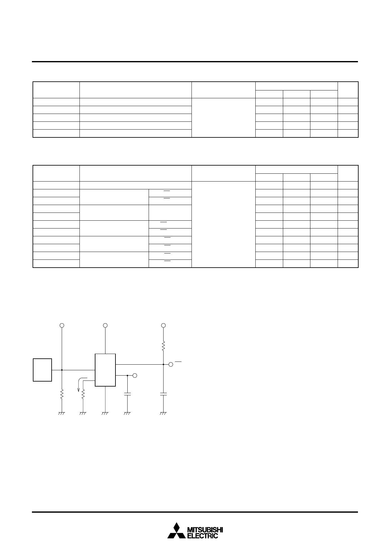
NOTE 6: TEST CIRCUIT
Input
VCC
VCC
(1)
P.G.
50Ω
DUT
RC
lref
RC=
360Ω
RL=100Ω
SQ15
(2)
CL=50pF
Q0~15
(2)
CL=50pF
(1) Characteristics of pulse generator (PG)
Rise time
: tr = 6ns
Fall time
: tf = 6ns
Output impedance : ZO =50Ω
(2) Capacitance CL includes the stray capacitance of the lead
wires and the probe input capacitance.
6
Share Link: 