M66503 Ver la hoja de datos (PDF) - MITSUBISHI ELECTRIC
Número de pieza
componentes Descripción
Fabricante
M66503 Datasheet PDF : 8 Pages
| |||
MITSUBISHI 〈DIGITAL ASSP〉
M66503ASP/AGP
16-BIT CONSTANT CURRENT LED DRIVER with SHIFT REGISTER AND LATCH
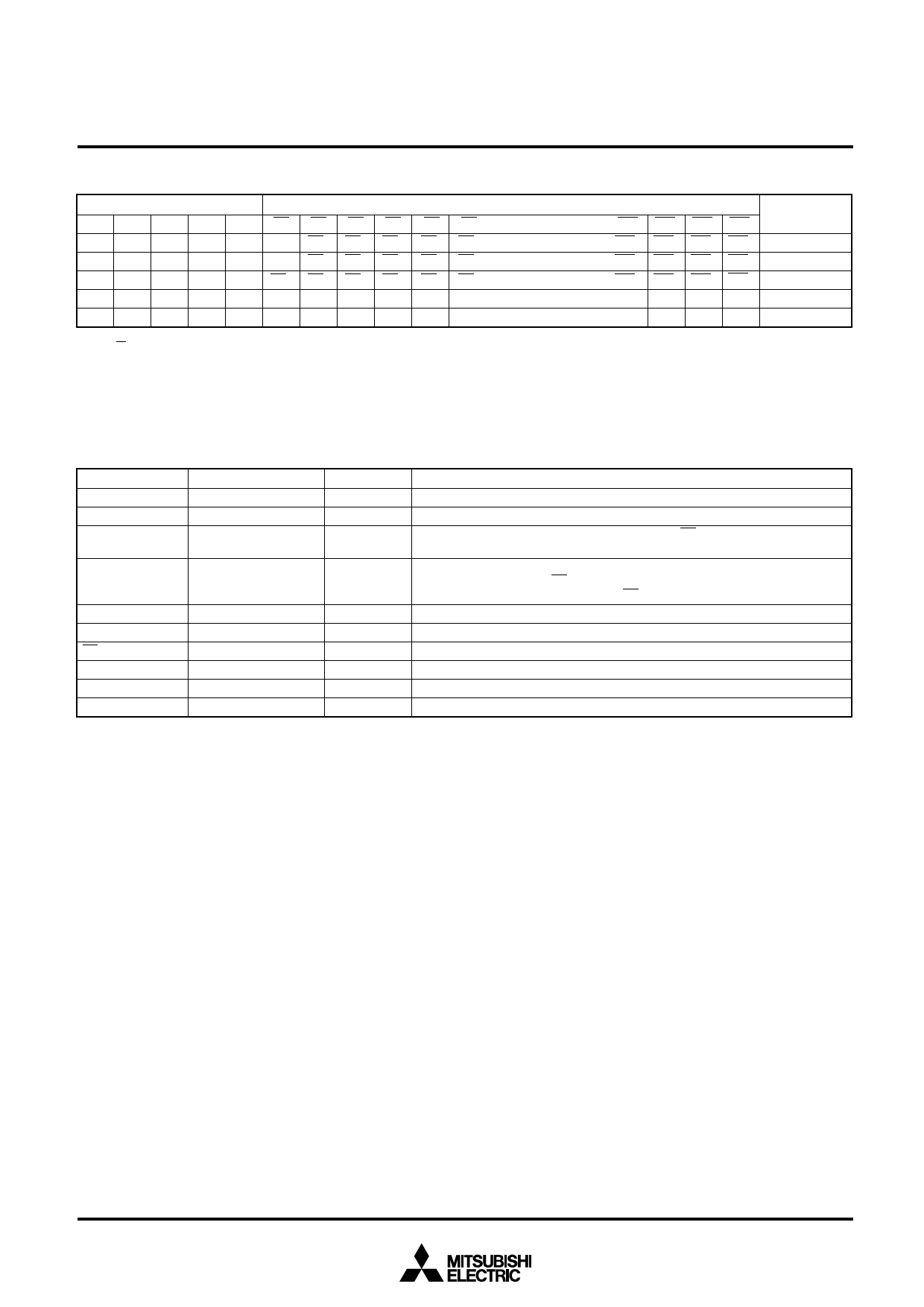
FUNCTION TABLE (Note 3)
Input
Parallel output
Serial output
CKS LE A OEA OEB Q0 Q1 Q2 Q3 Q4 Q5 ·································· Q12 Q13 Q14 Q15
SQ15
↑
H
H
L
H
L Q00 Q10 Q20 Q30 Q40 ·································· Q110 Q120 Q130 Q140
q140
↑
H
L
L
H
Z Q00 Q10 Q20 Q30 Q40 ·································· Q110 Q120 Q130 Q140
q140
X
L
X
L
H Q00 Q10 Q20 Q30 Q40 Q50 ·································· Q120 Q130 Q140 Q150
q15
X X L L L Z Z Z Z Z Z ·································· Z Z Z Z
q15
X X H H X L L L L L L ·································· L L L L
q15
Note 3: ↑ : Denotes change from “L” to “H”.
Q0 : Denotes state of Q output before change in CKS input.
x : Either “L” or “H”
q0 : Contents of shift register before change in CKS input
q : Contents of shift register
z : Denotes high impedance state
PIN DESCRIPTION
Pin
Name
A
Serial data input pin
CKS
Shift clock input pin
LE
Latch enable input pin
OEA
OEB
Output enable input
pins
SQ15
RC
Qn
VCC
GND1
GND2~5
Serial data output pin
Current setting input pin
LED connection pins.
Power supply pin
GND pin 1
GND pins 2-5
Input/Output
Input
Input
Input
Input
Output
Input
Output
Description
Shift register’s serial data input pin.
Clock input pin. Shifts data at leading edge.
If “H”, contents in shift register appear at output Qn, and if “L”, contents in shift
register are latched.
Output enable input pins.
If OEA =“H”, all outputs, Qn, are turned on.
If OEA =“L” and OEB =“L”, all outputs, Qn, are turned off.
Serial data output pin of shift register
Connect a resistor between the RC pin and GND to set the driving current.
Driver output pins. Connect LED’s cathodes to these pins.
Connect to positive power source (+5V).
GND for internal digital circuits.
GND for internal analog circuits.
3
Share Link: 