MXD1000PA45 Ver la hoja de datos (PDF) - Maxim Integrated
Número de pieza
componentes Descripción
Fabricante
MXD1000PA45 Datasheet PDF : 8 Pages
| |||
5-Tap Silicon Delay Line
tRISE
VIH
IN
VIL
OUT
PERIOD
tFALL
2.4V 2.4V
1.5V
1.5V
1.5V
0.6V
0.6V
tWI
tPHL
tPLH
1.5V 1.5V
(+5V)
VCC
0.1µF
TIME
MEASUREMENT
UNIT
IN
20%
50Ω
20%
MXD1000
20%
20%
20%
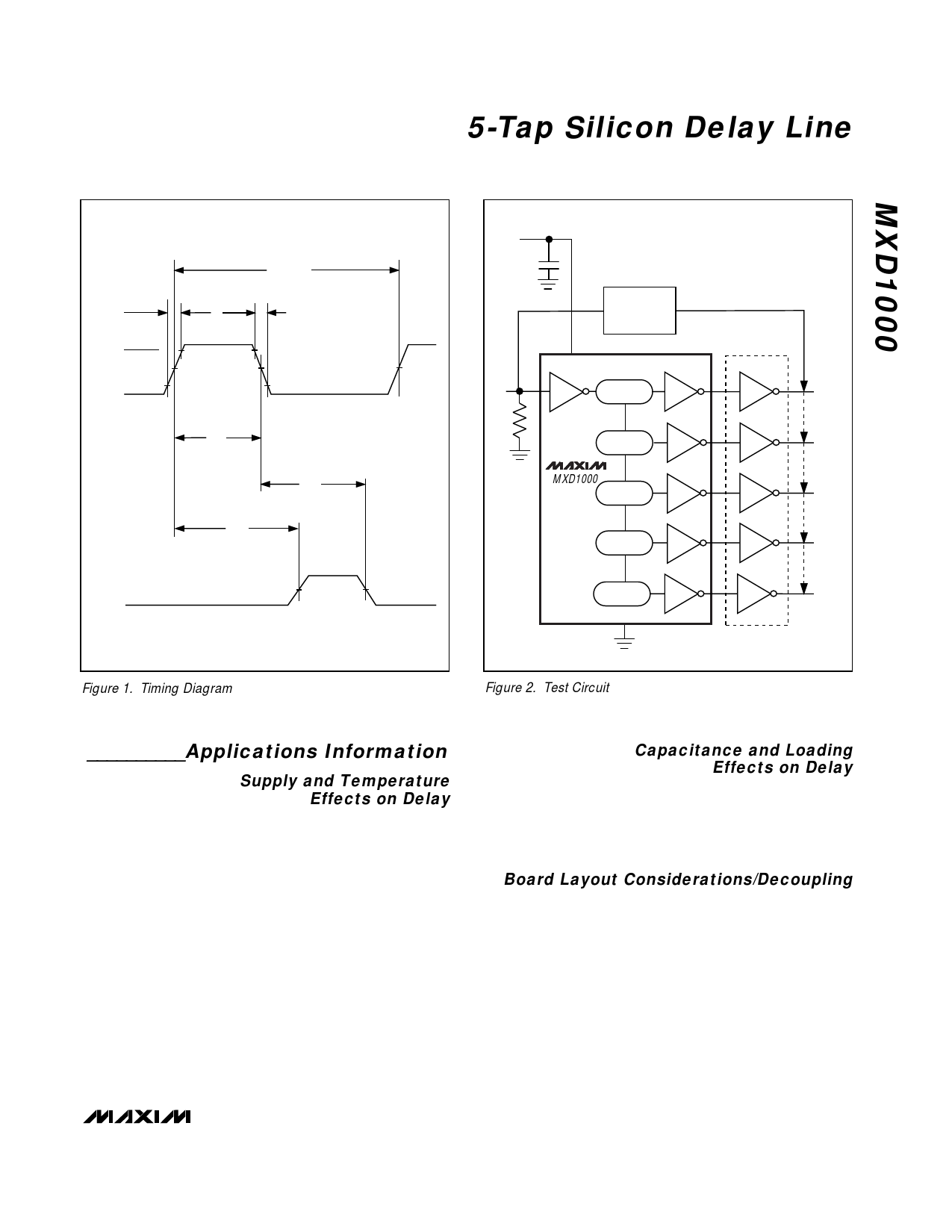
Figure 1. Timing Diagram
Figure 2. Test Circuit
TAP1
TAP2
TAP3
TAP4
TAP5
74FO4
__________Applications Information
Supply and Temperature
Effects on Delay
Variations in supply voltage may affect the MXD1000’s
fixed tap delays. Supply voltages beyond the specified
range may result with larger variations. The devices are
internally compensated to reduce the effects of temper-
ature variations. Although these devices might vary with
supply and temperature, the delays vary unilaterally,
which suggests that TAP3 can never be faster than
TAP2.
Capacitance and Loading
Effects on Delay
The output load can affect the tap delays. Larger
capacitances tend to lengthen the rising and falling
edges, thus increasing the tap delays. As the taps are
loaded with other logic devices, the increased load will
increase the tap delays.
Board Layout Considerations/Decoupling
The device should be driven with a source that can
deliver the required current for proper operation. A
0.1µF ceramic bypassing capacitor could be used. The
board should be designed to reduce stray capaci-
tance.
_______________________________________________________________________________________ 5
Share Link: 