MXD1000PA45 Ver la hoja de datos (PDF) - Maxim Integrated
Número de pieza
componentes Descripción
Fabricante
MXD1000PA45 Datasheet PDF : 8 Pages
| |||
5-Tap Silicon Delay Line
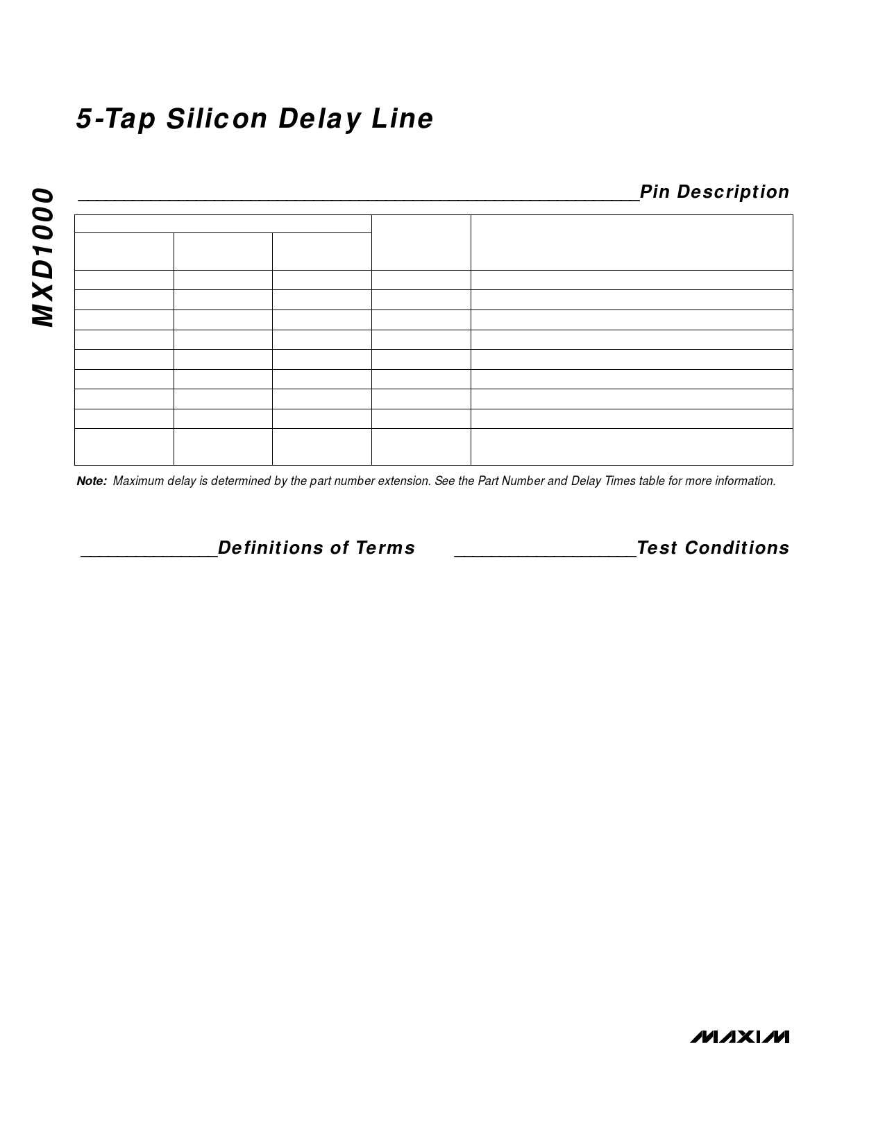
______________________________________________________________Pin Description
8-PIN
DIP/SO/µMAX
1
2
3
4
5
6
7
8
—
PIN
14-PIN DIP
1
4
6
7
8
10
12
14
2, 3, 5, 9, 11,
13
16-PIN SO
1
4
6
8
9
11
13
16
2, 3, 5, 7, 10,
12, 14, 15
NAME
IN
TAP2
TAP4
GND
TAP5
TAP3
TAP1
VCC
N.C.
FUNCTION
Signal Input
40% of specified maximum delay
80% of specified maximum delay
Device Ground
100% of maximum specified delay
60% of specified maximum delay
20% of specified maximum delay
Power-Supply Input
No Connection. Not internally connected.
Note: Maximum delay is determined by the part number extension. See the Part Number and Delay Times table for more information.
_______________Definitions of Terms
Period: The time elapsed between the first pulse’s
leading edge and the following pulse’s leading edge.
Pulse Width (tWI): The time elapsed on the pulse
between the 1.5V level on the leading edge and the
1.5V level on the trailing edge, or vice-versa.
Input Rise Time (tRISE): The time elapsed between
the 20% and 80% points on the input pulse’s leading
edge.
Input Fall Time (tFALL): The time elapsed between
the 80% and 20% points on the input pulse’s trailing
edge.
Time Delay, Rising (tPLH): The time elapsed between
the 1.5V level on the input pulse’s leading edge and the
corresponding output pulse’s leading edge.
Time Delay, Falling (tPHL): The time elapsed between
the 1.5V level on the input pulse’s trailing edge and the
corresponding output pulse’s trailing edge.
____________________Test Conditions
Ambient Temperature: +25°C ±3°C
Supply Voltage (VCC): +5V ±0.1V
Input Pulse:
High = 3.0V ±0.1V
Low = 0.0V ±0.1V
Source Impedance:
50Ω max
Rise and Fall Times: 3.0ns max
Pulse Width:
500ns max (1ns for -500)
Period:
1µs (2ns for -500)
Each output is loaded with a 74F04 input gate. Delay is
measured at the 1.5V level on the rising and falling
edges. The time delay due to the 74F04 is subtracted
from the measured delay.
4 _______________________________________________________________________________________
Share Link: 