TRA2525 Ver la hoja de datos (PDF) - ON Semiconductor
Número de pieza
componentes Descripción
Fabricante
TRA2525 Datasheet PDF : 8 Pages
| |||
TRA2525 MR3025
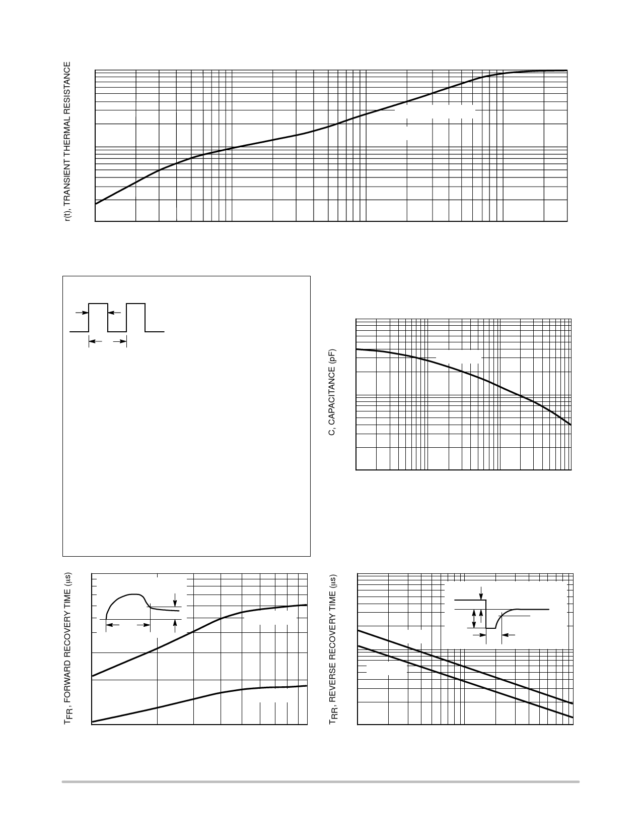
100
10–1
RqJC(t) = RqJC • r(t)
Note 1
10–2
0.1
1
10
t, TIME (ms)
Figure 6. Thermal Response
100
300
NOTE 1
Ppk
tp
t1
Ppk
DUTY CYCLE, D = tp/t1
PEAK POWER, Ppk is peak of an
equivalent square power pulse
To determine maximum junction temperature of the diode in a given
situation, the following procedure is recommended.
The temperature of the case should be measured using a thermocou-
ple placed on the case at the temperature reference point (see the
outline drawing on page 1). The thermal mass connected to the case
is normally large enough so that it will not significantly respond to heat
surges generated in the diode as a result of pulse operation once
steady state conditions are achieved.
Using the measured value of TC, the junction temperature may be
determined by:
TJ = TC + DTJC
Where DTJC is the increase in junction temperature above the case
temperature, it may be determined by:
DTJC = Ppk @ RqJC [D + (1 – D) @ r(t1 + tp) + r(tp) – r(t1)]
where:
r(t) = normalized value of transient thermal resistance at
time, t, from Figure 6, i.e.:
r(t1 + tp) = normalized value of transient thermal resistance
at time t1 + tp.
1000
100
TJ = 25°C
10
0.1
1
10
100
VR, REVERSE VOLTAGE (V)
Figure 7. Typical Capacitance
1
VF
TJ = 25°C
TFR
VFR
VFR = 1.0 V
VFR = 2.0 V
0.1
1
10
IF, FORWARD CURRENT (A)
Figure 8. Forward Recovery Time
100
IF = 1 A
10
IF = 10 A
IF
0
IR
TJ = 25°C
0.25 IR
TRR
1
0.1
1
10
IR/IF, RATIO OF REVERSE TO FORWARD CURRENT
Figure 9. Reverse Recovery Time
http://onsemi.com
4
Share Link: 