MCP6001RT-I/MS Ver la hoja de datos (PDF) - Microchip Technology
Número de pieza
componentes Descripción
Fabricante
MCP6001RT-I/MS Datasheet PDF : 28 Pages
| |||
MCP6001/2/4
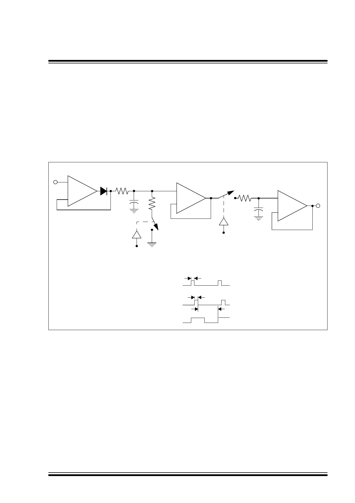
This voltage rate of change is less than the MCP6001/2/4
slew rate of 0.6 V/µs. When the input voltage swings
below the voltage across C1, D1 becomes reverse-
biased. This opens the feedback loop and rails the
amplifier. When the input voltage increases, the amplifier
recovers at its slew rate. Based on the rate of voltage
change shown in the above equation, it takes an
extended period of time to charge a 0.1 µF capacitor. The
capacitors need to be selected so that the circuit is not
limited by the amplifier slew rate. Therefore, the capaci-
tors should be less than 40 µF and a stabilizing resistor
(RISO) needs to be properly selected. (Refer to
Section 4.3 “Capacitive Loads”).
VIN
+ 1/2
D1
MCP6002
RISO VC1
–
Op Amp A
C1
R1
+ 1/2
MCP6002
–
Op Amp B
RISO VC2
C2
+
MCP6001
–
VOUT
Op Amp C
Clear
Switch
Sample
Switch
tSAMP
Sample Signal
tCLEAR
Clear Signal
tDETECT
CLK
FIGURE 4-8:
Peak Detector with Clear and Sample CMOS Analog Switches.
© 2005 Microchip Technology Inc.
DS21733F-page 11
Share Link: 