MAX7316 Ver la hoja de datos (PDF) - Maxim Integrated
Número de pieza
componentes Descripción
Fabricante
MAX7316
Maxim Integrated

MAX7316 Datasheet PDF : 24 Pages
| |||
10-Port I/O Expander with LED Intensity
Control, Interrupt, and Hot-Insertion Protection
WRITE TO OUTPUT PORTS REGISTERS (BLINK PHASE 0 REGISTERS/BLINK PHASE 1 REGISTERS)
SCL 1 2 3 4 5 6 7 8 9
SLAVE ADDRESS
COMMAND BYTE
SDA S A6 A5 A4 A3 A2 A1 A0 0 A 0 0 0 0 0 0 0 1 A MSB
DATA1
LSB A MSB
DATA2
LSB A P
START CONDITION
P7–P0
R/W ACKNOWLEDGE FROM SLAVE
ACKNOWLEDGE FROM SLAVE
ACKNOWLEDGE FROM SLAVE
DATA1 VALID
tDV
tDV
STOP
CONDITION
DATA2 VALID
READ FROM INPUT PORTS REGISTERS
SCL
123456789
SLAVE ADDRESS
COMMAND BYTE
SDA S A6 A5 A4 A3 A2 A1 A0 1 A MSB
DATA1
START CONDITION
P7–P0
DATA1
R/W ACKNOWLEDGE FROM SLAVE
DATA2
tDH
DATA3
LSB A MSB
DATA4
LSB NA P
ACKNOWLEDGE FROM MASTER
DATA4
tDS
STOP CONDITION
NO ACKNOWLEDGE FROM
MASTER
INTERRUPT VALID/RESET
SCL 1 2 3 4 5 6 7 8
SLAVE ADDRESS
SDA S A6 A5 A4 A3 A2 A1 A0 1
9
COMMAND BYTE
A MSB
DATA2
LSB A MSB
DATA4
LSB NA P
START CONDITION
P7–P0
DATA1
R/W ACKNOWLEDGE FROM SLAVE
DATA2
ACKNOWLEDGE FROM MASTER
DATA3
STOP CONDITION
NO ACKNOWLEDGE FROM
MASTER
INT
tIV
tIR tIV
tIR
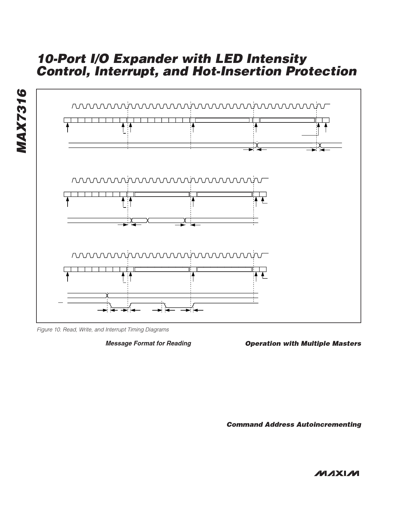
Figure 10. Read, Write, and Interrupt Timing Diagrams
Message Format for Reading
The MAX7316 is read using the MAX7316’s internally
stored command byte as an address pointer the same
way the stored command byte is used as an address
pointer for a write. The pointer autoincrements after
each data byte is read using the same rules as for a
write (Table 2). Thus, a read is initiated by first configur-
ing the MAX7316’s command byte by performing a
write (Figure 7). The master can now read n consecu-
tive bytes from the MAX7316 with the first data byte
being read from the register addressed by the initial-
ized command byte. When performing read-after-write
verification, remember to reset the command byte’s
address because the stored command byte address
has been autoincremented after the write (Table 2). A
diagram of a read from the input ports register is shown
in Figure 10 reflecting the states of the ports.
Operation with Multiple Masters
If the MAX7316 is operated on a 2-wire interface with
multiple masters, a master reading the MAX7316 should
use a repeated start between the write, which sets the
MAX7316’s address pointer, and the read(s) that takes
the data from the location(s) (Table 2). This is because it
is possible for master 2 to take over the bus after master
1 has set up the MAX7316’s address pointer but before
master 1 has read the data. If master 2 subsequently
changes the MAX7316’s address pointer, then master
1’s delayed read can be from an unexpected location.
Command Address Autoincrementing
The command address stored in the MAX7316 circu-
lates around grouped register functions after each data
byte is written or read (Table 2).
10 ______________________________________________________________________________________
Share Link: