MAX7319 Ver la hoja de datos (PDF) - Maxim Integrated
Número de pieza
componentes Descripción
Fabricante
MAX7319 Datasheet PDF : 15 Pages
| |||
MAX7319
I2C Port Expander with Eight Inputs
and Maskable Transition Detection
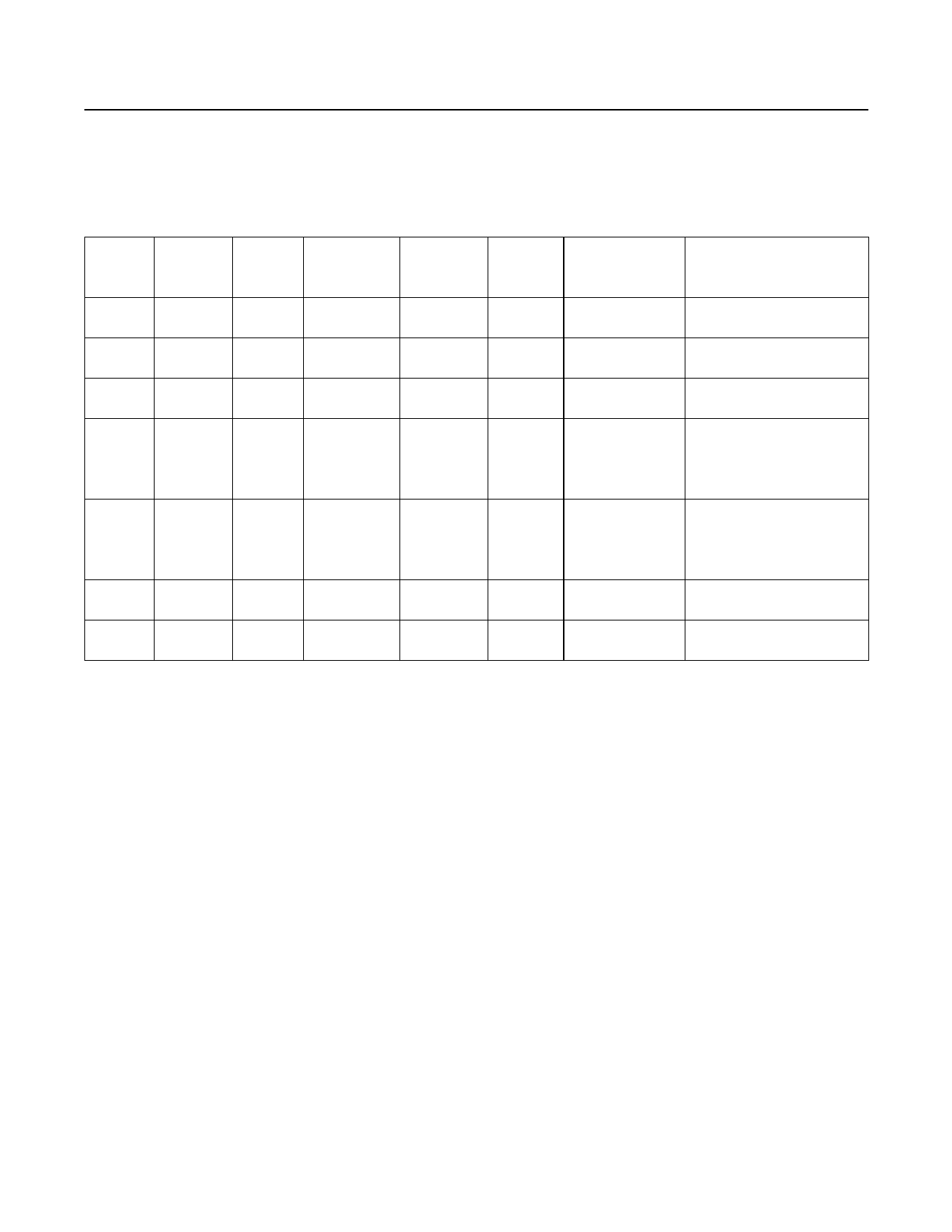
Table 2. Read and Write Access to Eight-Port Expander Family
PART
I2C SLAVE
ADDRESS
INPUTS
MAX7319 110xxxx
8
MAX7320 101xxxx
—
MAX7321 110xxxx Up to 8
MAX7322 110xxxx
4
MAX7323 110xxxx Up to 4
MAX7328 0100xxx Up to 8
MAX7329 0111xxx Up to 8
INTERRUPT
MASK
Yes
—
—
Yes
—
—
—
OPEN-
RAIN
OUTPUTS
—
—
Up to 8
—
Up to 4
Up to 8
Up to 8
PUSH-
PULL I2C DATA WRITE
OUTPUTS
I2C DATA READ
—
<I7–I0 interrupt
mask>
<I7–I0 port inputs>
<I7–I0 transition flags>
8
<O7–O0 port
outputs>
<O7–O0 port inputs>
—
<P7–P0 port
outputs>
<P7–P0 port inputs>
<P7–P0 transition flags>
<O7, O6 outputs, <O7, O6, I5–I2, O1, O0
4
I5–I2 interrupt
mask, O1, O0
Port inputs>
<0, 0, I5–I2 transition flags,
outputs>
0, 0>
<O7, O6, P5–P2, O1, O0
4
<port outputs>
Port inputs>
<0, 0, P5–P2 transition flags,
0, 0>
—
<P7–P0 port
outputs>
<P7–P0 port inputs>
—
<P7–P0 port
outputs>
<P7–P0 port inputs>
of the I2C specification. Therefore, address inputs AD2
and AD0 that are connected to SDA or SCL normally
appear at power-up to be connected to V+. The pullup
selection logic uses AD0 to select whether pullups are
enabled for ports I3–I0, and uses AD2 to select whether
pullups are enabled for ports I7–I4. The rule is that a
logic-high SDA or SCL connection selects the pullups,
while a logic-low deselects the pullups (Table 3). The
pullup configuration is correct on power-up for a standard
I2C configuration, where SDA and SCL are pulled up to
V+ by the external I2C pullup resistors.
There are circumstances where the assumption that
SDA = SCL = V+ on power-up is not true, for
example, in true hot-swap applications, in which there is
legitimate bus activity during power-up. Also, if SDA and
SCL are terminated with pullup resistors to a different
supply voltage than the MAX7319’s supply voltage, and
if that pullup supply rises later than the MAX7319’s
supply, then SDA or SCL may appear at power-up to be
connected to GND. In such applications, use the four
address combinations that are selected by connecting
address inputs AD2 and AD0 to V+ or GND (shown in
bold in Table 3). These selections are guaranteed to be
correct at power-up, independent of SDA and SCL
behavior. If one of the other 12 address combinations is
used, be aware that an unexpected combination of
pullups might be asserted until the first I2C
transmission (to any device, not necessarily the MAX7319)
is put on the bus.
Port Inputs
Port inputs switch at CMOS logic levels as determined by
the expander’s supply voltage, and are overvoltage toler-
ant to +6V, independent of the expander’s supply voltage.
Port-Input Transition Detection
All eight input ports are monitored for changes since
the expander was last accessed through the serial
interface. The state of the input ports is stored in an
internal “snapshot” register for transition monitoring.
The snapshot is continuously compared with the actual
input conditions, and if a change is detected for any
port input, an internal transition flag is set for that port.
The eight port inputs are sampled (internally latched
into the snapshot register) and the old transition flags
cleared during the I2C acknowledge of every MAX7319
read and write access. The previous port transition
flags are read through the serial interface as the sec-
ond byte of a 2-byte read sequence.
www.maximintegrated.com
Maxim Integrated │ 7
Share Link: 