MAX7319 Ver la hoja de datos (PDF) - Maxim Integrated
Número de pieza
componentes Descripción
Fabricante
MAX7319 Datasheet PDF : 15 Pages
| |||
MAX7319
I2C Port Expander with Eight Inputs
and Maskable Transition Detection
Slave Address
The MAX7319 has a 7-bit slave address (Figure 5). The
8th bit following the 7-bit slave address is the R/W bit. It
is low for a write command, and high for a read
command.
The 1st (A6), 2nd (A5), and 3rd (A4) bits of the MAX7319
slave address are always 1, 1, and 0. Connect AD2 and
AD0 to GND, V+, SDA, or SCL to select slave address
bits A3, A2, A1, and A0. The MAX7319 has 16 possible
slave addresses (Table 3), allowing up to 16 MAX7319
devices on an I2C bus
Accessing the MAX7319
I2C-interface access to the MAX7319 is summarized as
follows (Table 2):
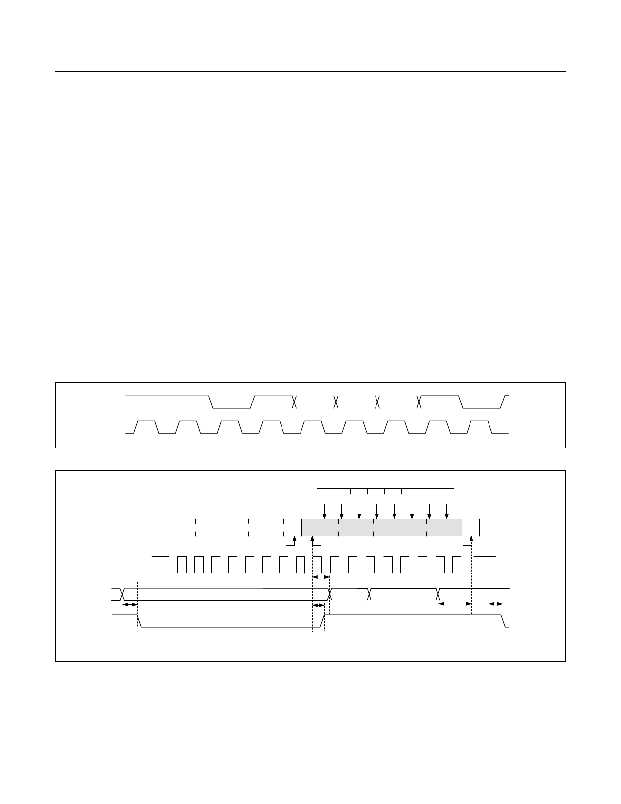
A single-byte read from the MAX7319 returns the
status of the eight input ports, and clears both the internal
transition flags and the INT output (Figure 7).
A 2-byte read returns the status of the eight input ports
(as for a single-byte read), followed by the transition
flags. The internal transition flags and the INT output
are cleared when the MAX7319 acknowledges the
slave address byte, but the previous transition flag data
is sent as the second byte (Figure 8).
A multibyte read (more than 2 bytes before the I2C
STOP bit) repeatedly returns the input port data,
alternating with the transition flags. As the input data is
resampled for each transmission, and the transition
flags are reset each time, a multibyte read continuously
returns the current data and identifies any changing
input ports.
If a port input data change occurs during the read
sequence, INT is reasserted after the I2C STOP bit. The
MAX7319 does not generate another interrupt during a
single-byte or multibyte read.
SDA
1
1
MSB
SCL
Figure 5. Slave Address
0
A3
A2
A1
A0
R/W
ACK
LSB
PORT INPUTS
I7 I6 I5 I4 I3 I2 I1 I0
S 1 1 0 MAX7319 SLAVE ADDRESS 1 A D7 D6 D5 D4 D3 D2 D1 D0 N P
R/W
PORT SNAPSHOT
PORT SNAPSHOT
SCL
PORT INPUT
tIV
INT OUTPUT
tPH
tIR
tPSU
tIP
INT REMAINS HIGH UNTIL STOP CONDITION
Figure 6. Reading from the MAX7319 (1 Data Byte)
S = START CONDITION
P = STOP CONDITION
SHADED = SLAVE TRANSMISSION
N = NOT ACKNOWLEDGE
www.maximintegrated.com
Maxim Integrated │ 10
Share Link: 