MAX7313 Ver la hoja de datos (PDF) - Maxim Integrated
Número de pieza
componentes Descripción
Fabricante
MAX7313
Maxim Integrated

MAX7313 Datasheet PDF : 26 Pages
| |||
16-Port I/O Expander with LED Intensity
Control, Interrupt, and Hot-Insertion Protection
as an input or an output. Reading an input ports regis-
ter latches the current-input logic level of the affected
eight ports. Transition detection allows all ports config-
ured as inputs to be monitored for changes in their
logic status. The action of reading an input ports regis-
ter samples the corresponding 8 port bits’ input condi-
tions. This sample is continuously compared with the
actual input conditions. A detected change in input
condition causes the INT/O16 interrupt output to go
low, if configured as an interrupt output. The interrupt is
cleared either automatically if the changed input
returns to its original state, or when the appropriate
input ports register is read.
The INT/O16 pin can be configured as either an inter-
rupt output or as a 17th output port with the same static
or blink controls as the other 16 ports (Table 4).
Port Output Control and LED Blinking
The two blink phase 0 registers set the output logic lev-
els of the 16 ports P0–P15 (Table 8). These registers
control the port outputs if the blink function is disabled.
A duplicate pair of registers, the blink phase 1 regis-
ters, are also used if the blink function is enabled
(Table 9). In blink mode, the port outputs can be
flipped between using the blink phase 0 registers and
the blink phase 1 registers using software control (the
blink flip flag in the configuration register) (Table 4).
PWM Intensity Control
The MAX7313 includes an internal oscillator, nominally
32kHz, to generate PWM timing for LED intensity con-
trol. PWM intensity control can be enabled on an out-
put-by-output basis, allowing the MAX7313 to provide
any mix of PWM LED drives and glitch-free logic out-
puts (Table 10). PWM can be disabled entirely, in
which case all output ports are static and the MAX7313
operating current is lowest because the internal oscilla-
tor is turned off.
PWM intensity control uses a 4-bit master control and 4
bits of individual control per output (Tables 13, 14). The
4-bit master control provides 16 levels of overall intensi-
ty control, which applies to all PWM-enabled output
ports. The master control sets the maximum pulse
width from 1/15 to 15/15 of the PWM time period. The
individual settings comprise a 4-bit number further
reducing the duty cycle to be from 1/16 to 15/16 of the
time window set by the master control.
For applications requiring the same PWM setting for all
output ports, a single global PWM control can be used
instead of all the individual controls to simplify the con-
trol software and provide 240 steps of intensity control
(Tables 10 and 13).
Standby Mode
When the serial interface is idle and the PWM intensity
control is unused, the MAX7313 automatically enters
standby mode. If the PWM intensity control is used, the
operating current is slightly higher because the internal
PWM oscillator is running. When the serial interface is
active, the operating current also increases because
the MAX7313, like all I2C slaves, has to monitor every
transmission.
Serial Interface
Serial Addressing
The MAX7313 operates as a slave that sends and
receives data through an I2C-compatible 2-wire inter-
face. The interface uses a serial data line (SDA) and a
serial clock line (SCL) to achieve bidirectional commu-
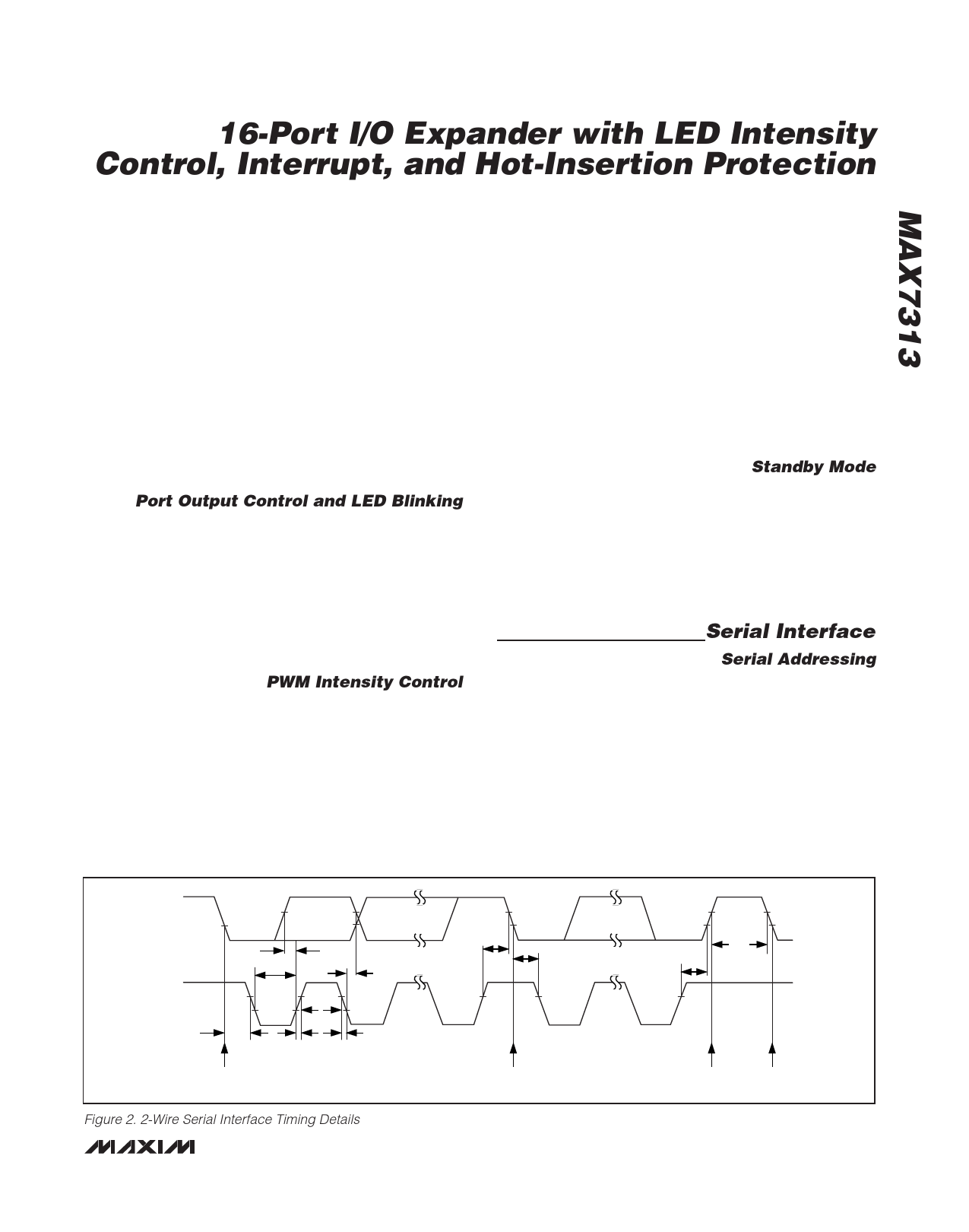
nication between master(s) and slave(s). A master (typ-
ically a microcontroller) initiates all data transfers to and
from the MAX7313 and generates the SCL clock that
synchronizes the data transfer (Figure 2).
The MAX7313 SDA line operates as both an input and
an open-drain output. A pullup resistor, typically 4.7kΩ,
is required on SDA. The MAX7313 SCL line operates
SDA
tLOW
tSU,DAT
SCL
tHD,STA
START CONDITION
tHIGH
tR
tF
tHD,DAT
tSU,STA
tHD,STA
REPEATED START CONDITION
tBUF
tSU,STO
STOP
START
CONDITION CONDITION
Figure 2. 2-Wire Serial Interface Timing Details
_______________________________________________________________________________________ 7
Share Link: