MAX7313 Ver la hoja de datos (PDF) - Maxim Integrated
Número de pieza
componentes Descripción
Fabricante
MAX7313
Maxim Integrated

MAX7313 Datasheet PDF : 26 Pages
| |||
16-Port I/O Expander with LED Intensity
Control, Interrupt, and Hot-Insertion Protection
COMMAND BYTE IS STORED ON RECEIPT OF
STOP CONDITION
ACKNOWLEDGE FROM MAX7313
D15 D14 D13 D12 D11 D10 D9 D8
S
SLAVE ADDRESS
0A
COMMAND BYTE
AP
R/W
ACKNOWLEDGE FROM MAX7313
Figure 7. Command Byte Received
HOW COMMAND BYTE AND DATA BYTE MAP INTO
MAX7313'S REGISTERS
ACKNOWLEDGE FROM MAX7313
ACKNOWLEDGE FROM MAX7313
D15 D14 D13 D12 D11 D10 D9 D8
ACKNOWLEDGE FROM MAX7313
D7 D6 D5 D4 D3 D2 D1 D0
S
SLAVE ADDRESS
0A
COMMAND BYTE
A
DATA BYTE
AP
1
R/W
BYTE
AUTOINCREMENT MEMORY ADDRESS
Figure 8. Command and Single Data Byte Received
HOW COMMAND BYTE AND DATA BYTE MAP INTO
MAX7313'S REGISTERS
ACKNOWLEDGE FROM MAX7313
ACKNOWLEDGE FROM MAX7313
D15 D14 D13 D12 D11 D10 D9 D8
ACKNOWLEDGE FROM MAX7313
D7 D6 D5 D4 D3 D2 D1 D0
S
SLAVE ADDRESS
0A
COMMAND BYTE
A
DATA BYTE
AP
N
R/W
BYTES
AUTOINCREMENT MEMORY ADDRESS
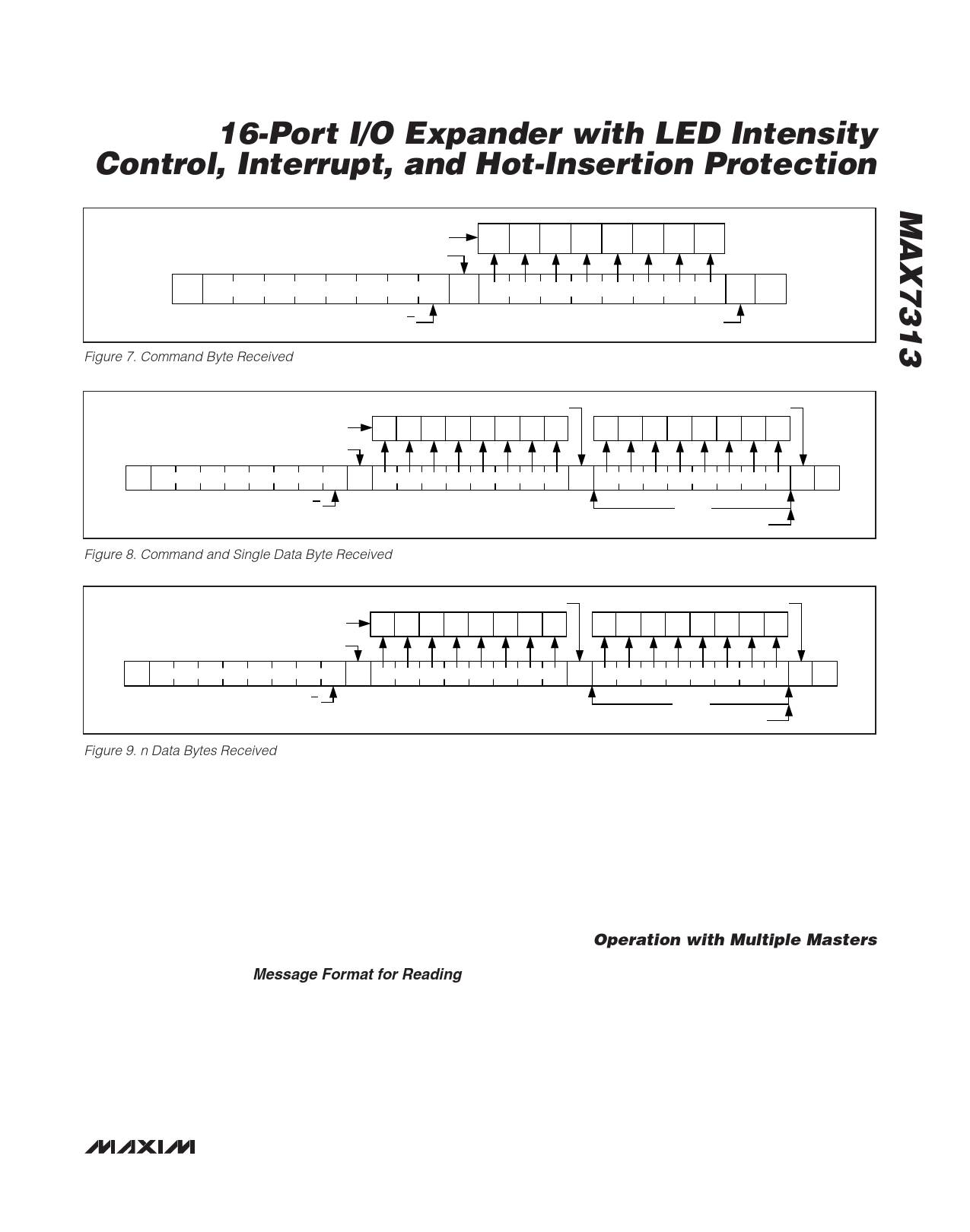
Figure 9. n Data Bytes Received
Any bytes received after the command byte are data
bytes. The first data byte goes into the internal register
of the MAX7313 selected by the command byte (Figure
8). If multiple data bytes are transmitted before a STOP
condition is detected, these bytes are generally stored
in subsequent MAX7313 internal registers because the
command byte address autoincrements (Table 2). A
diagram of a write to the output ports registers (blink
phase 0 registers or blink phase 1 registers) is given in
Figure 10.
Message Format for Reading
The MAX7313 is read using the MAX7313’s internally
stored command byte as an address pointer the same
way the stored command byte is used as an address
pointer for a write. The pointer autoincrements after
each data byte is read using the same rules as for a
write (Table 2). Thus, a read is initiated by first configur-
ing the MAX7313’s command byte by performing a
write (Figure 7). The master can now read n consecu-
tive bytes from the MAX7313 with the first data byte
being read from the register addressed by the initial-
ized command byte. When performing read-after-write
verification, remember to reset the command byte’s
address because the stored command byte address
has been autoincremented after the write (Table 2). A
diagram of a read from the input ports registers is
shown in Figure 10 reflecting the states of the ports.
Operation with Multiple Masters
If the MAX7313 is operated on a 2-wire interface with
multiple masters, a master reading the MAX7313 should
use a repeated start between the write, which sets the
MAX7313’s address pointer, and the read(s) that takes
the data from the location(s) (Table 2). This is because it
is possible for master 2 to take over the bus after master
1 has set up the MAX7313’s address pointer but before
master 1 has read the data. If master 2 subsequently
changes the MAX7313’s address pointer, then master
1’s delayed read can be from an unexpected location.
______________________________________________________________________________________ 11
Share Link: