MAX7312 Ver la hoja de datos (PDF) - Maxim Integrated
Número de pieza
componentes Descripción
Fabricante
MAX7312
Maxim Integrated

MAX7312 Datasheet PDF : 16 Pages
| |||
2-Wire-Interfaced 16-Bit I/O Port Expander
with Interrupt and Hot-Insertion Protection
ABSOLUTE MAXIMUM RATINGS
V+ to GND ................................................................-0.3V to +6V
I/O0–I/O15 as Inputs ....................................(GND - 0.3V) to +6V
SCL, SDA, AD0, AD1, AD2, INT...................(GND - 0.3V) to +6V
Maximum V+ Current ......................................................+250mA
Maximum GND Current ...................................................-250mA
DC Input Current on I/O0–I/O15 .......................................±20mA
DC Output Current on I/O0–I/O15 ....................................±80mA
Continuous Power Dissipation (TA = +70°C)
24-Pin Wide SO (derate 11.8mW/°C above +70°C) ....941mW
24-Pin SSOP (derate 8.0mW/°C above +70°C) ...........640mW
24-Pin TSSOP (derate 12.2mW/°C above +70°C) .......975mW
24-Pin Thin QFN (derate 20.8mW/°C above +70°C) .1668mW
Operating Temperature Range .........................-40°C to +125°C
Junction Temperature ......................................................+150°C
Storage Temperature Range .............................-65°C to +150°C
Lead Temperature (soldering, 10s) .................................+300°C
Stresses beyond those listed under “Absolute Maximum Ratings” may cause permanent damage to the device. These are stress ratings only, and functional
operation of the device at these or any other conditions beyond those indicated in the operational sections of the specifications is not implied. Exposure to
absolute maximum rating conditions for extended periods may affect device reliability.
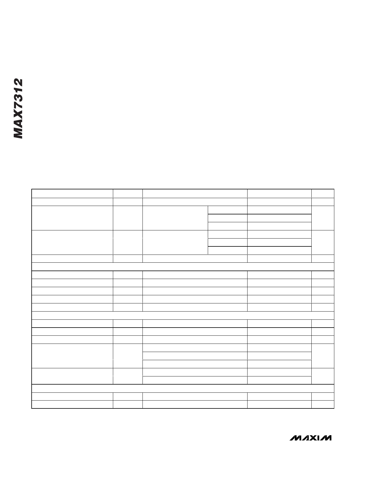
DC ELECTRICAL CHARACTERISTICS
(V+ = 2V to 5.5V, TA = -40°C to +125°C, unless otherwise noted. Typical values are at V+ = 3.3V, TA = +25°C.) (Note 1)
PARAMETER
Supply Voltage
Supply Current
Standby Current
Power-On Reset Voltage
SCL, SDA
Input Voltage Low
Input Voltage High
Low-Level Output Voltage
Leakage Current
Input Capacitance
I/O_
Input Voltage Low
Input Voltage High
Input Leakage Current
Low-Level Output Current
High Output Current
AD0, AD1, AD2
Input Voltage Low
Input Voltage High
SYMBOL
V+
I+
ISTBY
VPOR
CONDITIONS
All I/Os unloaded,
fSCL = 400kHz
All I/Os unloaded,
fSCL = 0
V+ = 2V
V+ = 3.3V
V+ = 5.5V
V+ = 2V
V+ = 3.3V
V+ = 5.5V
VIL
VIH
VOL
ISINK = 6mA
IL
VIL
VIH
ISINK
ISOURCE
TA = -40°C to +85°C
V+ = 2V, VOL = 0.5V
V+ = 3.3V, VOL = 0.5V
V+ = 5V, VOL = 0.5V
V+ = 3.3V, VOH = 2.4V
V+ = 5V, VOH = 4.5V
VIL
VIH
MIN TYP MAX UNITS
2
5.5
V
23
35
43
60
µA
80
120
2.3
11
2.9
12
µA
3.8 15.5
1.4
1.7
V
0.7 x V+
0.3 x V+
V
V
0.4
V
-1
+1
µA
10
pF
0.8
V
1.8
V
-1
+1
µA
8.5
17
17
32
mA
43
29
41
mA
31
0.7 x V+
0.3 x V+
V
V
2 _______________________________________________________________________________________
Share Link: