MAX7301(2003) Ver la hoja de datos (PDF) - Maxim Integrated
Número de pieza
componentes Descripción
Fabricante
MAX7301 Datasheet PDF : 18 Pages
| |||
4-Wire-Interfaced, 2.5V to 5.5V, 20-Port and
28-Port I/O Expander
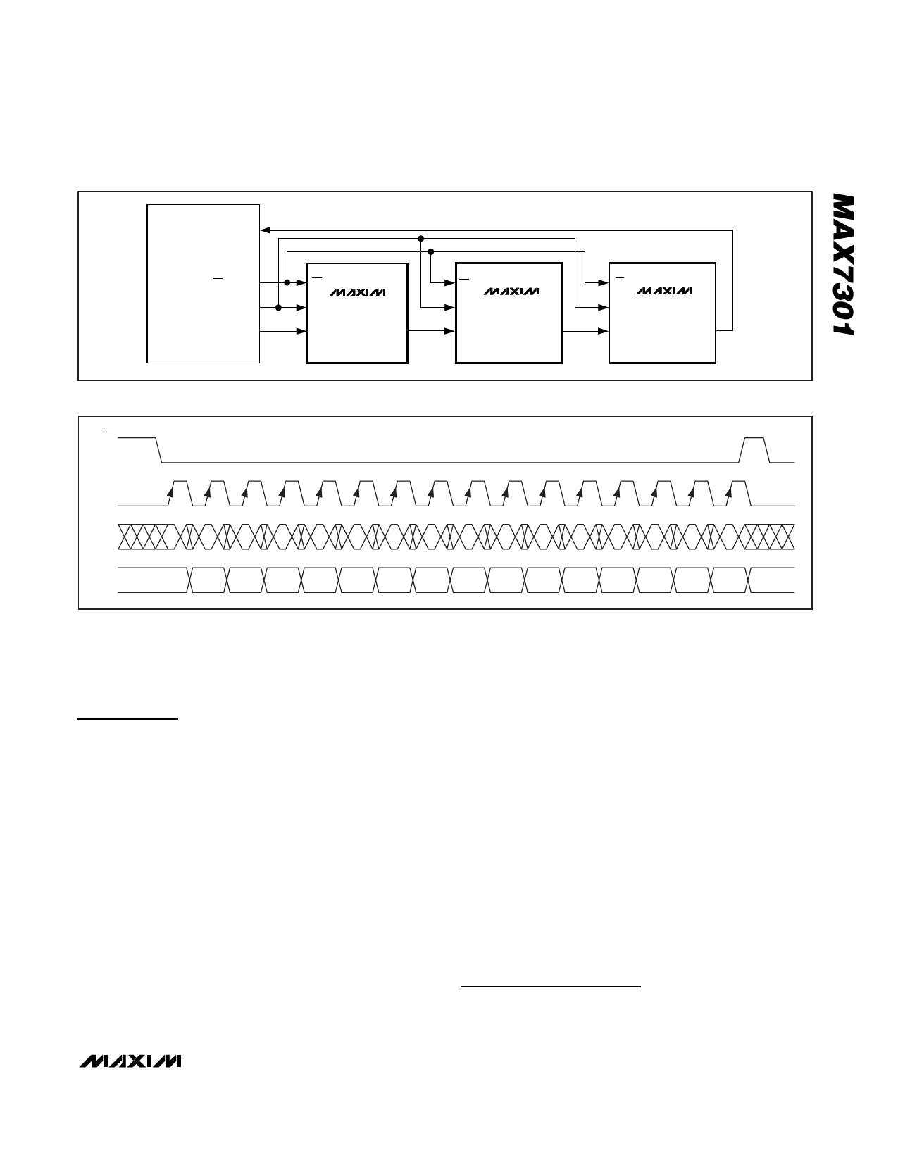
MICROCONTROLLER
SERIAL DATA INPUT
SERIAL CS OUTPUT
SERIAL CLOCK OUTPUT
SERIAL DATA OUTPUT
CS
SCLK MAX7301
DIN
DOUT
CS
SCLK
MAX7301
DIN
DOUT
CS
SCLK MAX7301
DIN
DOUT
Figure 3. Daisy-Chain Arrangement for Controlling Multiple MAX7301s
CS
SCLK
DIN
D15
=0
D14
D13
D12
D11
D10
D9
D8
D7
D6
D5
D4
D3
D2
D1
D0
DOUT
D15 = 0
.
Figure 4. Transmission of a16-Bit Write to the MAX7301
External Component RISET
The MAX7301 uses an external resistor, RISET, to set
internal biasing. Use a resistor value of 39kΩ.
Applications Information
Low-Voltage Operation
The MAX7301 operates down to 2V supply voltage
(although the sourcing and sinking currents are not
guaranteed), providing that the MAX7301 is powered
up initially to at least 2.5V to trigger the device’s internal
reset, and also that the serial interface is constrained to
10Mbps.
SPI Routing Considerations
The MAX7301’s SPI interface is guaranteed to operate
at 26Mbps on a 2.5V supply, and on a 5V supply typi-
cally operates at 50Mbps. This means that transmission
line issues should be considered when the interface
connections are longer than 100mm, particularly with
higher supply voltages. Ringing manifests itself as
communication issues, often intermittent, typically due
to double clocking due to ringing at the SCLK input. Fit
a 1kΩ to 10kΩ parallel termination resistor to either
GND or V+ at the DIN, SCLK, and CS input to damp
ringing for moderately long interface runs. Use line-
impedance matching terminations when making con-
nections between boards.
PC Board Layout Considerations
Ensure that all the MAX7301 GND connections are
used. A ground plane is not necessary, but may be
useful to reduce supply impedance if the MAX7301 out-
puts are to be heavily loaded. Keep the track length
from the ISET pin to the RISET resistor as short as possi-
ble, and take the GND end of the resistor either to the
ground plane or directly to the ground pins.
Power-Supply Considerations
The MAX7301 operates with power-supply voltages of
2.5V to 5.5V. Bypass the power supply to GND with a
0.047µF capacitor as close to the device as possible.
Add a 1µF capacitor if the MAX7301 is far away from
the board’s input bulk decoupling capacitor.
Chip Information
TRANSISTOR COUNT: 30,316
PROCESS: CMOS
_______________________________________________________________________________________ 9
Share Link: 