MAX7036(2010) Ver la hoja de datos (PDF) - Maxim Integrated
Número de pieza
componentes Descripción
Fabricante
MAX7036 Datasheet PDF : 13 Pages
| |||
300MHz to 450MHz ASK Receiver
with Internal IF Filter
an error in the reference frequency. A crystal designed
to operate at a higher load capacitance than the value
specified for the oscillator is always pulled higher in fre-
quency. Adding capacitance to increase the load
capacitance on the crystal increases the start-up time
and may prevent oscillation altogether.
In actuality, the oscillator pulls every crystal. The crys-
tal’s natural frequency is really below its specified fre-
quency, but when loaded with the specified load
capacitance, the crystal is pulled and oscillates at its
specified frequency. This pulling is already accounted
for in the specification of the load capacitance.
Additional pulling can be calculated if the electrical
parameters of the crystal are known. The frequency
pulling is given by:
fP=
CM
2
⎛
⎝⎜⎜ CCASE
1
+ CLOAD
−
CCASE
1
+ CSPEC
⎞
⎠⎟⎟
×
106
where:
fp is the amount the crystal frequency is pulled in
ppm.
CM is the motional capacitance of the crystal.
CCASE is the case capacitance.
CSPEC is the specified load capacitance.
CLOAD is the actual load capacitance.
When the crystal is loaded, as specified (i.e., CLOAD =
CSPEC), the frequency pulling equals zero.
It is possible to use an external reference oscillator in
place of a crystal to drive the VCO. AC-couple the exter-
nal oscillator to XTAL1 with a 1000pF capacitor. Drive
XTAL1 with a signal level of approximately -10dBm. AC-
couple XTAL2 to ground with a 1000pF capacitor.
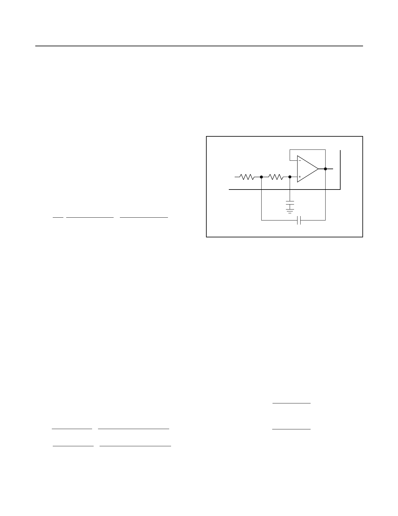
IF Filter
The IF filter is a 2nd-order Butterworth lowpass filter
preceded by a low-frequency DC block. The lowpass
filter is implemented as a Sallen-Key filter using an
internal op amp and two on-chip 22kΩ resistors. The
pole locations are set by the combination of the on-chip
resistors and two external capacitors (C9 and C10,
Figure 1). The values of these two capacitors for a 3dB
cutoff frequency of 400kHz are given below:
C9
=
1
(1.414)(R)(π)(fc
)
=
1
(1.414)(22kΩ)(3.14)(400kHz)
=
26pF
C10
=
1
(2.828)(R)(π)(fc
)
=
1
(2.828)(22kΩ)(3.14)(400kHz)
=
13pF
Because the stray shunt capacitance at each of the
pins (IFC1 and IFC2) on a typical PCB is approximately
2pF, choose the value of the external capacitors to be
approximately 2pF lower than the desired total capaci-
tance. Therefore, the practical values for C9 and C10
are 22pF and 10pF, respectively.
MAX7036
22kΩ
22kΩ
10
9
11
IFC1
IFC2
IFC3
C10
C9
Figure 1. Sallen-Key Lowpass IF Filter
Data Filter
The data filter is implemented as a 2nd-order lowpass
Sallen-Key filter. The pole locations are set by the combi-
nation of two on-chip resistors and two external capaci-
tors. Adjusting the value of the external capacitors
changes the corner frequency to optimize for different
data rates. Set the corner frequency to approximately
1.5 times the fastest Manchester expected data rate
from the transmitter. Keeping the corner frequency near
the data rate rejects any noise at higher frequencies,
resulting in an increase in receiver sensitivity.
The configuration shown in Figure 2 can create a
Butterworth or Bessel response. The Butterworth filter
offers a very flat amplitude response in the passband
and a rolloff rate of 40dB/decade for the two-pole filter.
The Bessel filter has a linear phase response, which
works with the coefficients in Table 1.
C5
=
b
a (100k)( π )( fc )
C6
=
a
4 (100k)( π )( fc )
where fC is the desired corner frequency.
_______________________________________________________________________________________ 9
Share Link: 