MAX6978 Ver la hoja de datos (PDF) - Maxim Integrated
Número de pieza
componentes Descripción
Fabricante
MAX6978
Maxim Integrated

MAX6978 Datasheet PDF : 13 Pages
| |||
8-Port, 5.5V Constant-Current LED Driver with
LED Fault Detection and Watchdog
OE is independent of the operation of the serial inter-
face. Data can be shifted into the serial-interface shift
register and latched regardless of the state of OE.
DOUT is the serial-data output, which shifts data out
from the MAX6978’s 8-bit shift register on the rising edge
of CLK. Data at DIN is propagated through the shift reg-
ister and appears at DOUT eight clock cycles later.
Watchdog
The MAX6978 includes a watchdog circuit that monitors
the CLK, DIN, and LE inputs. If there is no transition on
any one of these inputs for nominally 1s, then the output
latches are cleared and outputs OUT0–OUT7 go high
impedance like the initial power-up condition. This turns
off all LEDs connected to the outputs. The shift-register
data does not change, just the output-latch data.
The watchdog is intended to be used as a fail-safe fea-
ture for applications, which prefer a blank display to an
incorrect display if the serial interface fails. When the
watchdog triggers, the outputs remain off until the dri-
ver output latches are updated with data turning them
on. Recovery is therefore automatic if the transmission
failure is temporary, because the MAX6978 does not
lock up in the watchdog timeout state. The MAX6978
operates correctly when the serial interface is next acti-
vated, and the watchdog circuit is reset and starts
monitoring the serial interface again. The watchdog
function requires no software change to the application
driving the MAX6978.
LED Fault Detection
The MAX6978 includes circuitry that detects open-cir-
cuit LEDs automatically. An open-circuit fault occurs
when an output is programmed to sink current but less
than about 50% of the programmed current flows.
Open circuits are checked just after the rising edge of
LE, when new LED data is loaded into the output latch-
es from the shift register(s). If one or more output port is
detected with an open-circuit fault, then the 2 bits, D6
and D5, in the serial-interface shift register are both set
high. If no open-circuit faults are detected, then D6 and
D5 are both cleared low. The data in other 6-bit posi-
tions in the serial-interface shift register is not altered.
Fault status is automatically shifted out on DOUT when
the next data transmission is shifted in. LE is normally
taken high after all 8 bits of new LED data have been
clocked into the shift register, and so at that time,
DOUT is outputting data bit D7. On the next two rising
edges of CLK, the 2 fault status bits, D6 and D5, are
clocked out in that order, followed by the remaining 5
unchanged data bits D4 to D0.
A typical fault-detecting application tests all the shifted
out data. Bits D0–D4 and D7 are checked against the
originally transmitted data to check data link integrity.
Bits D5 and D6 are checked first to see that they con-
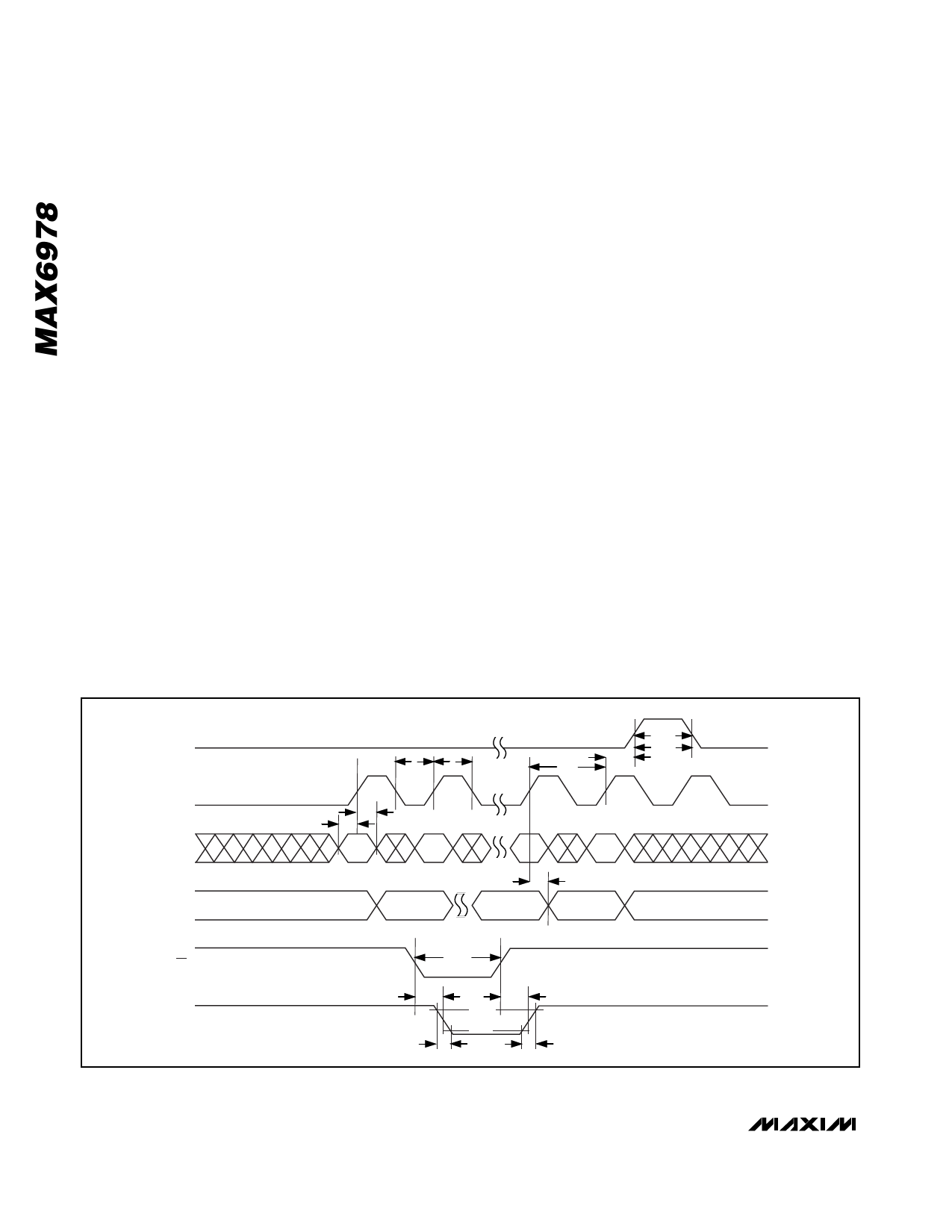
LE
CLK
DIN
DOUT
tCL
tCH
tDH
tDS
D7
D6
tLW
tLF
tLS
tCP
D1
tDO
D0
D7
OE
OUT_
tOEW
tOEL
tOEH
80%
.
20%
tf
tr
Figure 2. 4-Wire Serial-Interface Timing Diagram
8 _______________________________________________________________________________________
Share Link: