MAX470 Ver la hoja de datos (PDF) - Maxim Integrated
Número de pieza
componentes Descripción
Fabricante
MAX470 Datasheet PDF : 16 Pages
| |||
Two-Channel, Triple/Quad
RGB Video Switches and Buffers
(a)
75Ω CABLE
75Ω
75Ω CABLE
SOURCE:
TEKTRONIX
1910 DIGITAL GENERATOR
(b)
75Ω
75Ω CABLE
MAX469/MAX470
DUT
75Ω
75Ω CABLE
MAX467/MAX468
75Ω
DUT
AV = 2
150Ω
75Ω
75Ω
MEASUREMENT:
TEKTRONIX VM700
VIDEO MEASUREMENT
SET
75Ω CABLE
75Ω
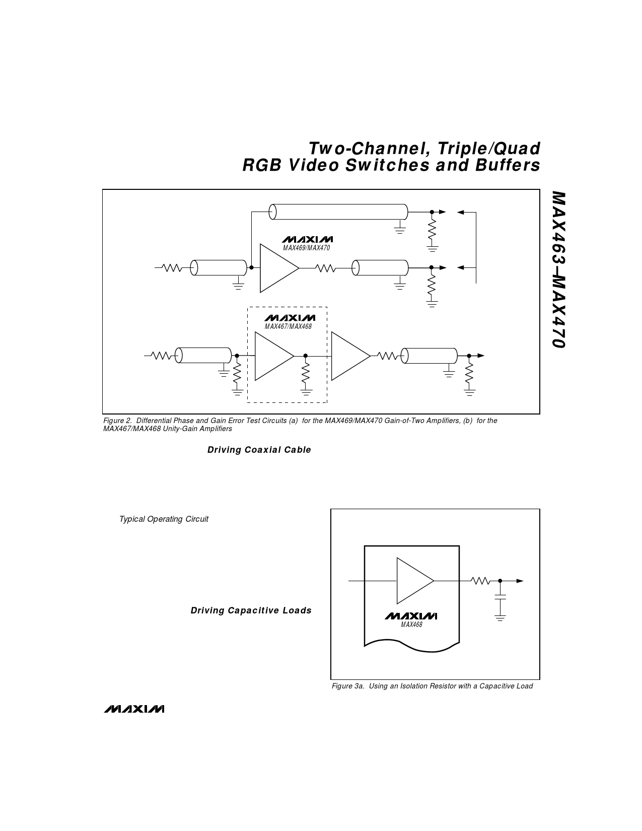
Figure 2. Differential Phase and Gain Error Test Circuits (a) for the MAX469/MAX470 Gain-of-Two Amplifiers, (b) for the
MAX467/MAX468 Unity-Gain Amplifiers
Driving Coaxial Cable
High-speed performance, excellent output current
capability, and an internally fixed gain of two make the
MAX465/MAX466/MAX469/MAX470 ideal for driving
50Ω or 75Ω back-terminated coaxial cables. The
MAX465/MAX466/MAX469/MAX470 will drive a 150Ω
load (75Ω back-terminated cable) to ±2.5V.
The Typical Operating Circuit shows the MAX465/MAX466
driving four back-terminated 75Ω video cables. The
back-termination resistor (at each amplifier output) pro-
vides impedance matching at the driven end of the
cable to eliminate signal reflections. It forms a voltage
divider with the load impedance, which attenuates the
signal at the cable output by one-half. The amplifier
operates with an internal 2V/V closed-loop gain to pro-
vide unity gain at the cable’s output.
Driving Capacitive Loads
Driving large capacitive loads increases the likelihood
of oscillation in most amplifier circuits. This is especially
true for circuits with high loop-gains, like voltage follow-
ers. The amplifier’s output impedance and the capaci-
tive load form an RC filter that adds a pole to the loop
response. If the pole frequency is low enough, as
when driving a large capacitive load, the circuit phase
margin is degraded and oscillation may occur.
The MAX463–MAX470 phase margin and capacitive-
load driving performance are optimized by internal
compensation. When driving capacitive loads greater
than 50pF, connect an isolation resistor between the
amplifier output and the capacitive load, as shown in
Figure 3.
AV = 1
12Ω
IN_
OUT_
100pF
MAX468
Figure 3a. Using an Isolation Resistor with a Capacitive Load
_______________________________________________________________________________________ 9
Share Link: 