MAX3996 Ver la hoja de datos (PDF) - Maxim Integrated
Número de pieza
componentes Descripción
Fabricante
MAX3996 Datasheet PDF : 16 Pages
| |||
3.0V to 5.5V, 2.5Gbps VCSEL
and Laser Driver
Table 1. Typical Fault Conditions
PIN
MON2
BIAS
TC, MODSET
FAULT CONDITION
VMON2 > 400mV
VBIAS < 400mV
VMODSET or VTC < 200mV
Smooth-Start
During startup, the laser does not emit light, and the
APC loop is not closed. The smooth-start circuit pulls
the MD pin to approximately 2.5V during the POR delay
and while TX_DISABLE is high. This causes the power-
control amplifier to shut off the bias transistor. When
POR delay is over and TX_DISABLE is low, the MD pin
is released and pulled to GND by RSET because there
is no laser power and thus no monitor diode current.
The output voltage of the power-control amplifier then
begins to increase. A capacitor attached to COMP
(CCOMP) slows the slew rate and allows a controlled
increase in bias current (Figure 11). Maxim recom-
mends CCOMP = 0.1µF.
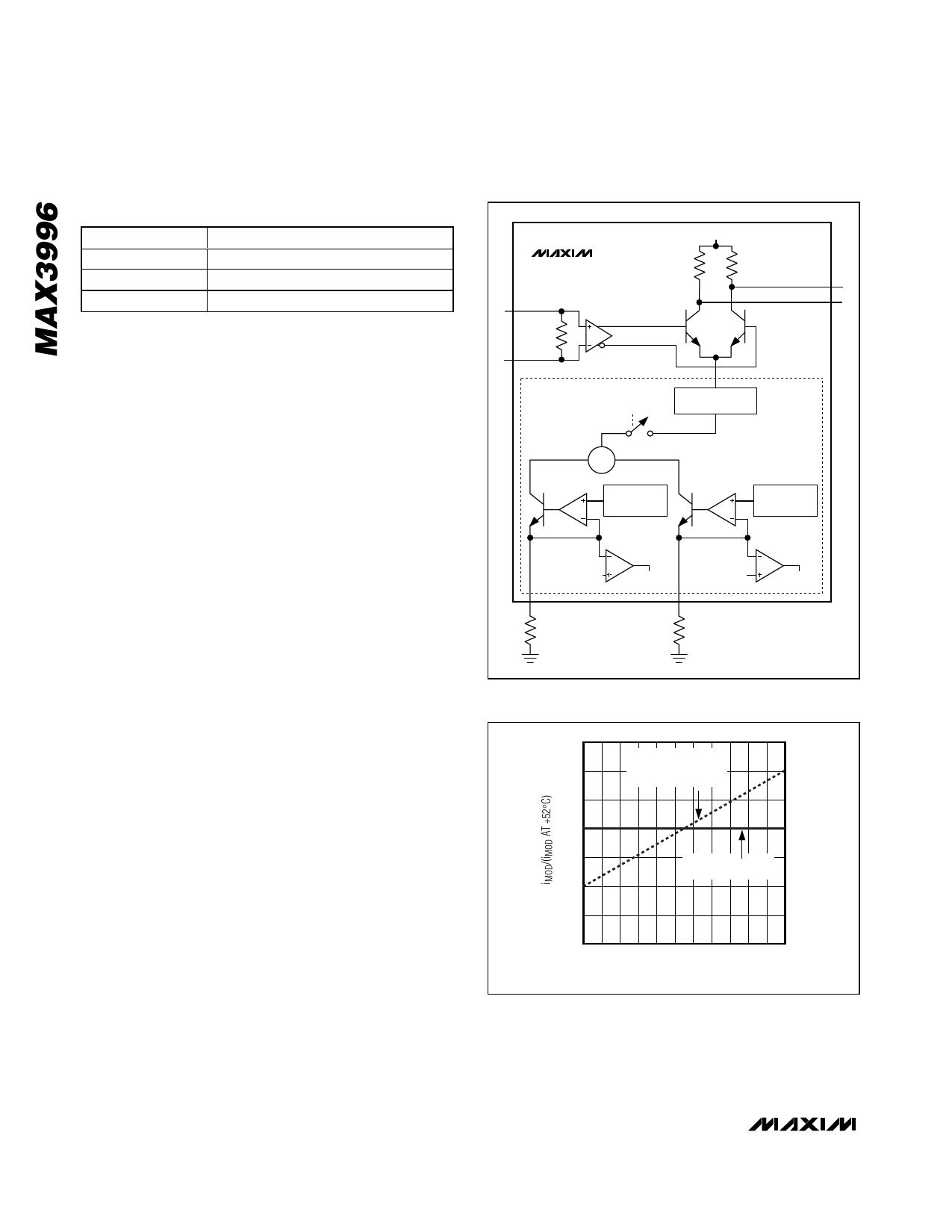
Modulation Circuitry
The modulation circuitry consists of an input buffer, a
current mirror, and a high-speed current switch (Figure
5). The modulator drives up to 30mA of modulation cur-
rent into a 25Ω load.
Many of the modulator performance specifications
depend on total modulator current. To ensure good driver
performance, the voltage at either OUT+ or OUT- must
not be less than VCC - 1V.
The amplitude of the modulation current is set with resis-
tors at the MODSET and temperature coefficient (TC)
pins. The resistor at MODSET (RMOD) programs the
temperature-stable portion of the modulation current,
and the resistor at TC (RTC) programs the temperature-
increasing portion of the modulation current. Figure 6
shows modulation current as a function of temperature
for two extremes: RTC is open (the modulation current
has zero temperature coefficient), and RMOD is open
(the modulation temperature coefficient is 4000ppm/°C).
Intermediate temperature coefficient values of the mod-
ulation current can be obtained as described in the
Design Procedure section. Table 2 is the RTC and RMOD
selection table.
Safety Circuitry
The safety circuitry contains a disable input, a fault
latch, and fault detectors (Figure 7). This circuitry moni-
tors the operation of the laser driver and forces a shut-
down if a single-point fault is detected. A single-point
fault can be a short to VCC or GND, or between any two
VCC
MAX3996
50Ω
50Ω
OUT+
IN+
INPUT BUFFER
CURRENT
SWITCH
OUT-
100Ω
IN-
ENABLE
Σ
CURRENT AMPLIFIER
96X
MODULATION
CURRENT
GENERATOR
1.2V REFERENCE
4000ppm/°C
1.2V REFERENCE
0ppm/°C
200mV
TC
RTC
TC FAULT
200mV
MODSET
RMOD
MODSET
FAULT
Figure 5. Modulation Circuitry
1.3
RTC ≥ 1.9kΩ
1.2
RMOD = OPEN
TEMPCO = 4000ppm/°C
1.1
1.0
0.9
RTC = OPEN
TEMPCO = 50ppm/°C
0.8
0.7
0.6
0 10 20 30 40 50 60 70 80 90 100 110
JUNCTION TEMPERATURE (°C)
Figure 6. Modulation Current vs. Temperature for Maximum
and Minimum Temperature Coefficient
8 _______________________________________________________________________________________
Share Link: 