MAX3996 Ver la hoja de datos (PDF) - Maxim Integrated
Número de pieza
componentes Descripción
Fabricante
MAX3996 Datasheet PDF : 16 Pages
| |||
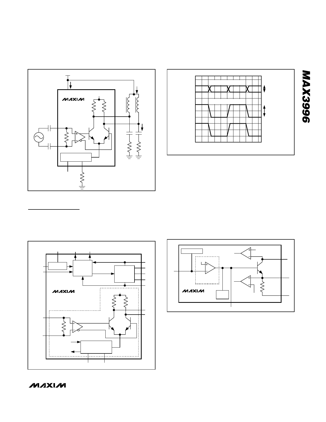
3.0V to 5.5V, 2.5Gbps VCSEL
and Laser Driver
3.0V TO 5.5V
ICC
VCC
VCC
MAX3996 ROUT
0.01µF
IN+
VID
RIN
0.01µF
IN-
MODULATION CURRENT
GENERATOR
ROUT
OUT-
OUT+
0.01µF
25Ω
TC
*MURATA
BLM11HA102SG
MODSET
RMOD
iOUT
FERRITE
BEAD*
iMOD
0.01µF
25Ω
Figure 1. Output Load for AC Specification
Detailed Description
The MAX3996 contains a bias generator with automatic
power control and smooth start, a laser modulator, a
power-on reset (POR) circuit, and safety circuitry
(Figure 3).
VOLTS
VIN+
VIN-
VID = VIN+ - VIN-
CURRENT
iMOD
SINGLE-ENDED SIGNAL
DIFFERENTIAL SIGNAL
100mVP-P MIN
1100mVP-P MAX
200mVP-P MIN
2200mVP-P MAX
TIME
Figure 2. Required Input Signal and Modulation-Current Polarity
Bias Generator
Figure 4 shows the bias generator circuitry that con-
tains a power-control amplifier, smooth-start circuitry,
and two bias-fault sensors. The power-control amplifier
combined with an internal NPN transistor provides DC
laser current to bias the laser in a light-emitting state.
The APC circuitry adjusts the laser bias current to main-
tain average power over temperature and changing
laser properties. The smooth-start circuitry prevents
current spikes to the laser during power-up or enable,
ensuring compliance with safety requirements and
extending the life of the laser.
VCC
FAULT SHDNDRV
PORDLY POR CIRCUIT
TX_DISABLE
SAFETY
CIRCUITRY
BIAS ENABLE
BIAS
GENERATOR
WITH SMOOTH
START
MAX3996
VCC
50Ω
50Ω
IN+
INPUT BUFFER
LASER
MODULATION
100Ω
IN-
MODULATION
ENABLE
MODULATION
FAULT
MODULATION CURRENT
GENERATOR
TC
MODSET
BIAS
MD
COMP
MON1
MON2
OUT-
OUT+
Figure 3. Laser Driver Functional Diagram
SMOOTH START
1.1V
BIAS
FAULT 1
MD
POWER-CONTROL
AMPLIFIER
MAX3996
BIAS
DISABLE
BIAS
FAULT 2
COMP
400mV
BIAS
MON2
400mV
RMON (11Ω)
MON1
Figure 4. Bias Circuitry
The MD input is connected to the anode of a monitor
diode, which is used to sense laser power. The BIAS
output is connected to the cathode of the laser through
an inductor or ferrite bead. The power-control amplifier
drives a transistor to control the laser’s bias current. In
a fault condition (Table 1), the base of the bias-driving
transistor is pulled low to ensure that bias current is
turned off.
_______________________________________________________________________________________ 7
Share Link: 