MAX3996 Ver la hoja de datos (PDF) - Maxim Integrated
Número de pieza
componentes Descripción
Fabricante
MAX3996 Datasheet PDF : 16 Pages
| |||
3.0V to 5.5V, 2.5Gbps VCSEL
and Laser Driver
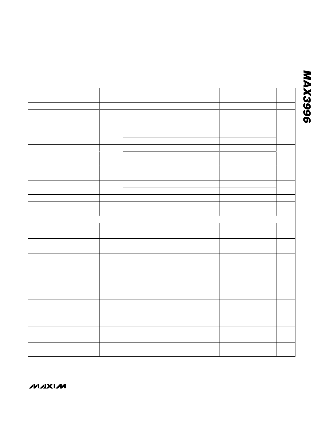
ELECTRICAL CHARACTERISTICS (continued)
(VCC = 3.0V to 5.5V, TA = 0°C to +70°C, unless otherwise noted. Typical values are at VCC = 3.3V, TC pin not connected, TA =
+25°C.) (Figure 1)
PARAMETER
SYMBOL
CONDITIONS
MIN TYP MAX UNITS
Minimum Modulation Current
Maximum Modulation Current
iMOD
iMOD
RL ≤ 25Ω
30
40
2
mAP-P
mAP-P
Accuracy of Modulation Current
(Part-to-Part Variation)
RMODSET = 2.37kΩ
(iMOD ≈ 30mAP-P into 25Ω)
-10
+10
%
iMOD = 5mA into 25Ω, 20% to 80% (Note 3)
54
100
Edge Transition Time
Deterministic Jitter
tr, tf
iMOD = 10mA into 25Ω, 20% to 80% (Note 3)
iMOD = 30mA into 25Ω, 20% to 80% (Note 3)
iMOD = 5mA into 25Ω (Notes 2, 3)
iMOD = 10mA into 25Ω (Notes 2, 3)
55
125
ps
65
130
17
35
14
22
psP-P
Random Jitter
iMOD = 30mA into 25Ω (Notes 2, 3)
(Note 3)
9
20
2
8
psRMS
Modulation Current During Fault iMOD_OFF
15
200 µAP-P
Modulation Current Tempco
Input Resistance
Output Resistance
RIN
ROUT
Tempco = MAX, RMOD = open
Tempco = MIN, RTC = open
Differential
Single ended; outputs to VCC
4000
50
ppm/°C
85
115
Ω
42
50
58
Ω
Input Common-Mode Voltage
SAFETY FEATURES (See Typical Operating Characteristics)
VCC - 0.3
V
MODSET and TC Pin
Fault Threshold
200
mV
BIAS Pin Fault Threshold
A fault will be triggered if VBIAS is less than
300
400
mV
this voltage
Excessive Bias Current Fault
A fault will be triggered if VMON2 exceeds
this voltage
400
440
mV
TX Disable Time
TX Disable Negate Time
Reset Initialization Time
t_off
t_on
t_init
Time from rising edge of TX_DISABLE to
IBIAS = IBIAS_OFF and iMOD = iMOD_OFF (Note 3)
Time from falling edge of TX_DISABLE to
IBIAS and iMOD at 95% of steady state (Note 3)
From power ON or negation of FAULT using
TX_DISABLE. Time to set FAULT = low, iMOD =
95% of steady state and IBIAS = 95% of steady
state (Note 3)
0.06
5
µs
37
500
µs
23
200
ms
Fault Assert Time
t_fault
Time from fault to FAULT = high, CFAULT
< 20pF, RFAULT = 4.7kΩ (Note 3)
14
50
µs
TX_DISABLE Reset
t_reset Time TX_DISABLE must be held high to
reset FAULT (Note 3)
0.01
1
µs
Note 1: Supply current excludes bias and modulation currents.
Note 2: Deterministic jitter is the peak-to-peak deviation from the ideal time crossings measured with a K28.5 bit pattern
00111110101100000101.
Note 3: AC characteristics guaranteed by design and characterization.
_______________________________________________________________________________________ 3
Share Link: 