MAX3996 Ver la hoja de datos (PDF) - Maxim Integrated
Número de pieza
componentes Descripción
Fabricante
MAX3996 Datasheet PDF : 16 Pages
| |||
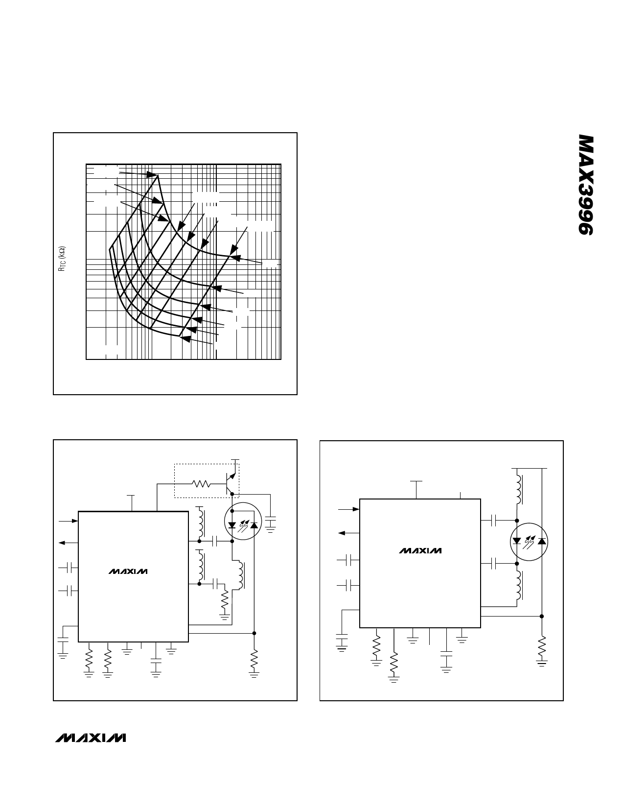
3.0V to 5.5V, 2.5Gbps VCSEL
and Laser Driver
1000
500ppm
1000ppm
1500ppm
2000ppm
2500ppm
3000ppm 3500ppm
10
5mA
RL = 25Ω
1
1
10mA
15mA
20mA
25mA
30mA
10
100
1000
RMOD (kΩ)
Figure 8. RTC vs. RMOD for Various Conditions
Determine Modulator Configuration
The MAX3996 can be used in several configurations.
For modulation currents less than 20mA, Maxim recom-
mends the configuration shown in the Typical
Application Circuit. Outputs greater than 20mA could
cause the voltage at the modulator output to be less
than VCC - 1V, which might degrade laser output. For
large currents, Maxim recommends the configuration in
Figure 9. A differential configuration is in Figure 10.
Designing the Bias Filter and
Output Pullup Beads
To reduce deterministic jitter, add a ferrite bead induc-
tor (L1) between the BIAS pin and the cathode of the
laser. Select L1 to have an impedance >100Ω between
f = 10MHz and f = 2GHz, and a DC resistance < 3Ω;
Maxim recommends the Murata BLM11HA102SG.
These inductors are also desirable for connecting the
OUT+ and OUT- pins to VCC.
Programming Laser Power and
Bias Fault Threshold
The IC is designed to drive a common anode laser with
a photodiode. A servo-control loop is formed by the
internal NPN bias-driving transistor, the laser diode, the
monitor diode (RSET), and the power-control amplifier
(Figure 11). The voltage at MD is stabilized to 1.1V. The
VCC
OPTIONAL SHUTDOWN
CIRCUITRY
VCC
1.8kΩ
VCC
TX_DISABLE
FAULT
VCC SHDNDRV
L2*
0.01µF
OUT-
VCC
0.01µF
IN+
0.01µF
IN-
MAX3996
L3*
0.01µF L1*
OUT+
25Ω
PORDLY
BIAS
MD
TC MODSET MON1 MON2 COMP GND
CPORDLY
N.C.
RTC RMOD
CCOMP
RSET
0.01µF
TX_DISABLE
FAULT
0.01µF
IN+
0.01µF
IN-
VCC
VCC
MAX3996
VCC
L2*
SHDNDRV
0.01µF
OUT+
0.01µF
OUT-
L1*
PORDLY
BIAS
MD
TC MODSET MON1 MON2 COMP GND
CPORDLY
RTC
N.C.
RSET
CCOMP
RMOD
*FERRITE BEAD
Figure 9. Large Modulation Current
*FERRITE BEAD
Figure 10. Differential Configuration
______________________________________________________________________________________ 11
Share Link: 