MAX3996 Ver la hoja de datos (PDF) - Maxim Integrated
Número de pieza
componentes Descripción
Fabricante
MAX3996 Datasheet PDF : 16 Pages
| |||
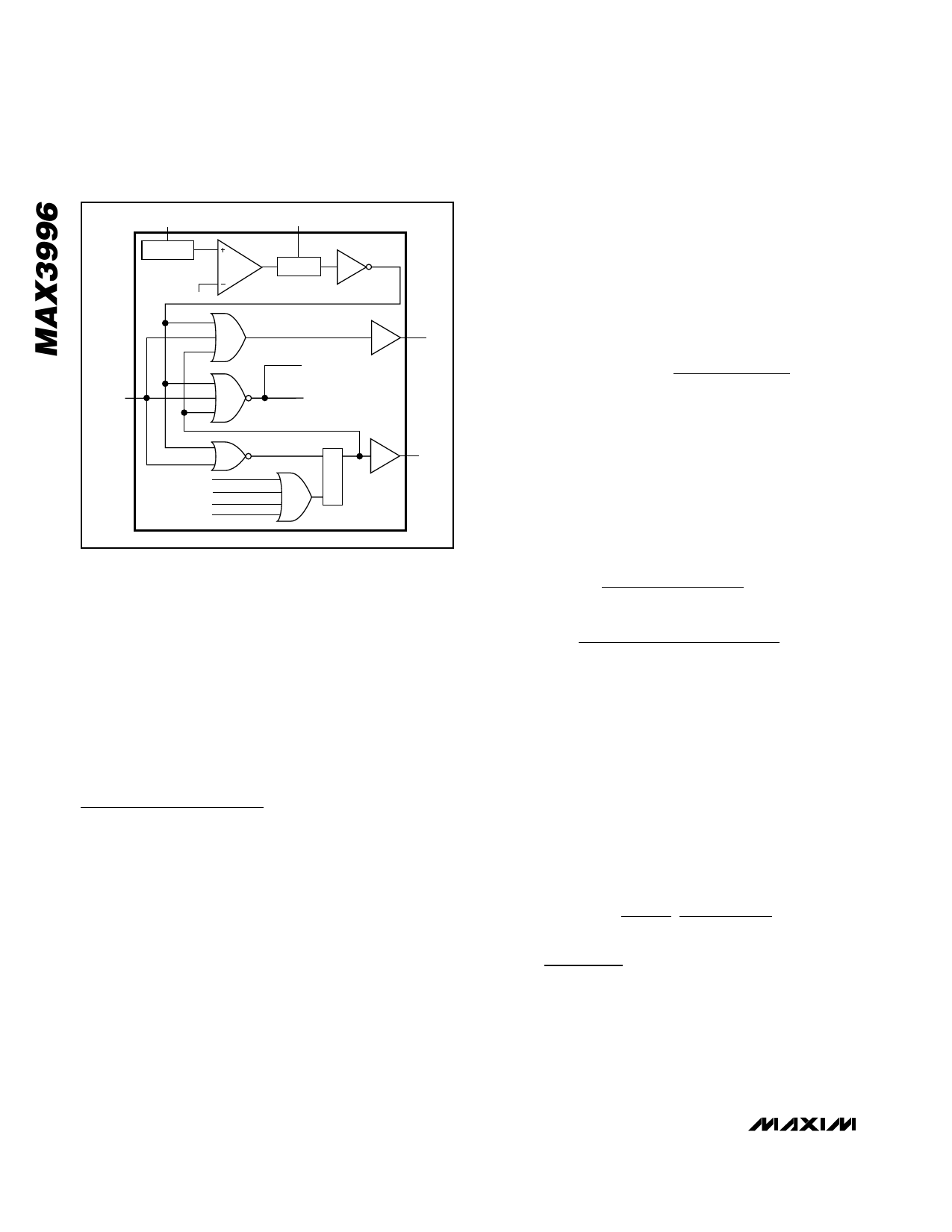
3.0V to 5.5V, 2.5Gbps VCSEL
and Laser Driver
VCC
STARTUP
VBG
TX_DISABLE
BIAS FAULT 1
BIAS FAULT 2
TC FAULT
MODSET FAULT
PORDLY
DELAY
BIAS ENABLE
MODULATOR
ENABLE
FAULT LATCH
RQ
S
SHDNDRV
FAULT
Figure 7. Safety Circuitry Functional Diagram
Latched Fault Output
An open-collector FAULT output is provided with the
MAX3996. This output is latched until the power is
switched off, then on, or until TX_DISABLE is switched
to HIGH and then LOW.
Power-On Reset
The MAX3996 contains an internal power-on reset
delay to reject noise on VCC during power-on or hot-
plugging. Adding capacitance to the PORDLY pin can
extend the delay. The POR comparator includes hys-
teresis to improve noise rejection.
Design Procedure
Select Laser
Select a communications-grade laser with a rise time of
260ps or better for 1.25Gbps or 130ps or better for
2.5Gbps applications. To meet the MAX3996’s AC
specifications, the voltage at both OUT+ and OUT-
must remain above VCC - 1V at all times.
Use a high-efficiency laser that requires low modulation
current and generates a low voltage swing. Trimming
the leads can reduce laser package inductance.
Typical package leads have inductance of 25nH per
inch (1nH/mm); this inductance causes a large voltage
swing across the laser. A compensation filter network
also can be used to reduce ringing, edge speed, and
voltage swing.
Programming Modulation Current
Resistors at the MODSET and TC pins set the ampli-
tude of the modulation current. The resistor RMOD sets
the temperature-stable portion of the modulation cur-
rent, and the resistor (RTC) sets the temperature-
increasing portion of the modulation current. To
determine the appropriate temperature coefficient from
the slope efficiency (η) of the laser, use the following
equation:
( ) LASER _ TEMPCO =
η70 − η25
× 106
[ppm / °C]
η25 70°C − 25°C
For example, if a laser has a slope efficiency η25 =
0.021mW/mA, which reduces to η70 = 0.018mW/mA.
Using the above equation will produce a laser tempco
of -3175ppm/°C.
To obtain the desired modulation current and tempco
for the device, the following equations can be used to
determine the required values of RMOD and RTC:
R TC
=
0.22
Tempco /106
×
iMOD
−
250Ω
( ) RMOD
=
Tempco /106
0.19 − 48 ×
RTC + 250Ω 52
Tempco
/
106
−
250Ω
where tempco = -laser tempco, 0 < tempco <
4000ppm/°C, and 2mA < iMOD < 30mA.
Figure 8 shows a family of curves derived from these
equations. The straight diagonal lines depict constant
tempcos. The curved lines represent constant modula-
tion currents. If no temperature compensation is
desired, leave TC open, and the equation for iMOD-
simplifies considerably.
The following equations were used to derive Figure 8 and
the equations at the beginning of this section.
iMOD
=
77 ×
50
50 + RL
1.15
RMOD + 250Ω
+
1.06
RTC + 250Ω
(1
+
0.004(T
−
25°C))Amps
10 ______________________________________________________________________________________
Share Link: 