MAX3657(2004) Ver la hoja de datos (PDF) - Maxim Integrated
Número de pieza
componentes Descripción
Fabricante
MAX3657 Datasheet PDF : 15 Pages
| |||
155Mbps Low-Noise Transimpedance
Amplifier
Understanding Bonding Coordinates and Physical Die
Size for more information on bond-pad coordinates.
Applications Information
Optical Power Relations
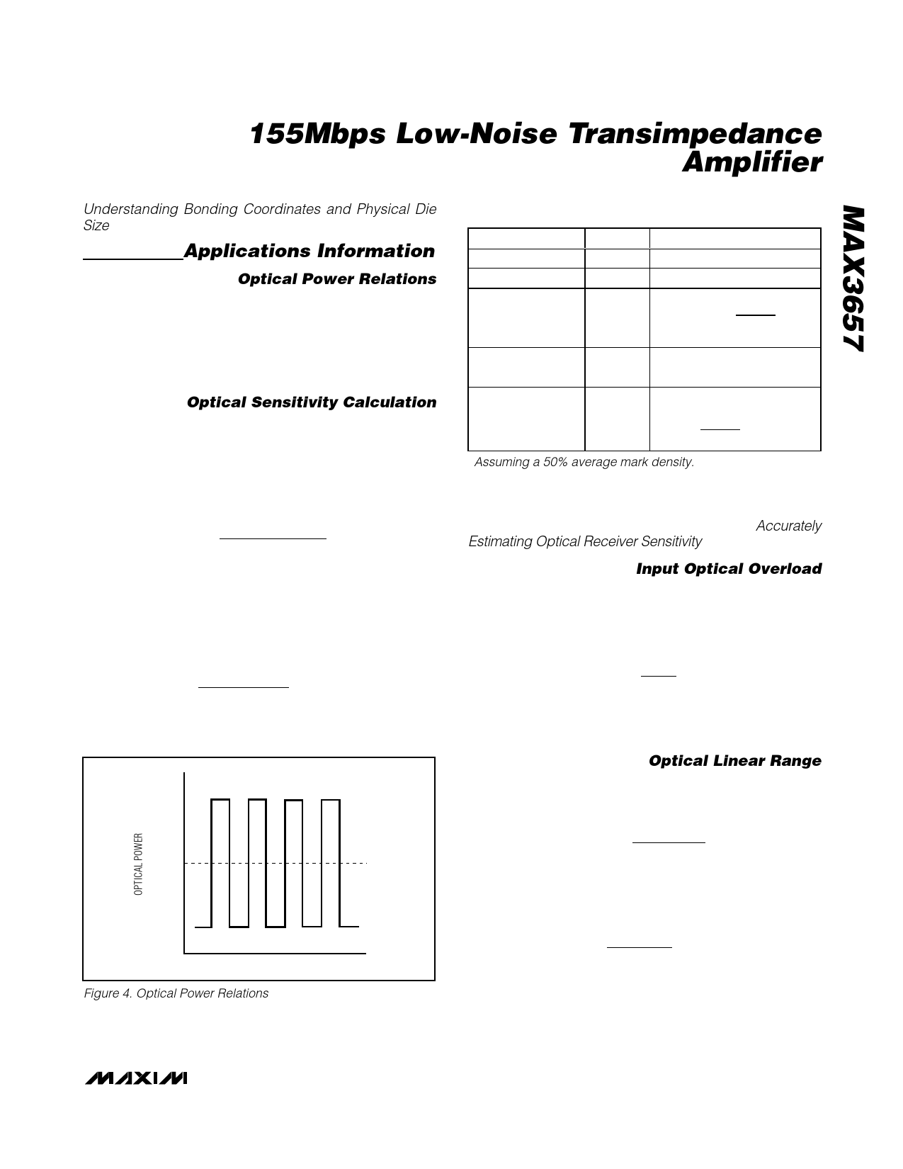
Many of the MAX3657 specifications relate to the input-
signal amplitude. When working with optical receivers,
the input is sometimes expressed in terms of average
optical power and extinction ratio. Figure 4 and Table 1
show relations that are helpful for converting optical
power to input signal when designing with the MAX3657.
Optical Sensitivity Calculation
The input-referred RMS noise current (in) of the
MAX3657 generally determines the receiver sensitivity.
To obtain a system bit-error rate (BER) of 1E-10, the
signal-to-noise ratio must always exceed 12.7. The
input sensitivity, expressed in average power, can be
estimated as:
Sensitivity
=
10log
12.7 x in x (re + 1)
2 x ρ x (re − 1)
x 1000
dBm
where ρ is the photodiode responsivity in A/W and in is
the RMS noise current in amps. For example, with pho-
todiode responsivity of 0.9A/W, an extinction ratio of 10
and 15nA input-referred noise, the sensitivity of the
MAX3657 is:
Sensitivity
=
10log
12.7 x 15nA x 11
2 x 0.9A / W x 9
x
1000
dBm
=
− 38dBm
P1
PAVG
P0
TIME
Figure 4. Optical Power Relations
Table 1. Optical Power Relations*
PARAMETER
Average power
Extinction ratio
Optical power
of a 1
SYMBOL
RELATION
PAVG
re
PAVG = (P0 + P1)/2
re = P1/P0
P1
PP11
==2P2APVAGVrGe r+e
r1e
re
+
1
Optical power
of a 0
P0
P0 = 2PAVG/(re + 1)
PPIINN
= P1 −
= P1
P0
−
P=02P=AVG
re
re
−
+
1
1
Optical modulation
amplitude
PIN
2PAVG
re
re + 1
*Assuming a 50% average mark density.
Actual results may vary depending on supply noise, out-
put filter, limiting amplifier sensitivity, and other factors
(refer to Maxim Application Note HFAN-3.0.0: Accurately
Estimating Optical Receiver Sensitivity).
Input Optical Overload
Overload is the largest input the MAX3657 accepts
while meeting the pulse-width distortion specification.
Optical overload can be estimated in terms of average
power with the following equation:
Overload
=
10log
2mA
2xρ
x 1000
dBm
For example, if photodiode responsivity is 1.0A/W, the
input overload is 0dBm.
Optical Linear Range
The MAX3657 has high gain, which limits the output for
large input signals. The MAX3657 operates in a linear
range for inputs not exceeding:
Linear Range
=
10log
2µA (re + 1)
2 x ρ (re − 1)
x 1000
dBm
For example, with photodiode responsivity of 0.9A/W
and an extinction ratio of 10 the linear range is:
Linear Range
=
10log
2µA x 11
2 x 0.9 x 9
x 1000
dBm
=
− 28dBm
_______________________________________________________________________________________ 9
Share Link: 