MAX3286 Ver la hoja de datos (PDF) - Maxim Integrated
Número de pieza
componentes Descripción
Fabricante
MAX3286 Datasheet PDF : 28 Pages
| |||
3.0V to 5.5V, 1.25Gbps/2.5Gbps
LAN Laser Drivers
impedance). This ensures that the PNP or NPN transistor
is turned off, removing the laser-bias current. (See the
Applications Information section.)
The REF pin provides a controlled reference voltage
dependent upon the voltage at MON. The voltage at REF
is VREF = 2.65 - 2.25(VCC - VMON). A resistor connected
at REF determines the laser power when APC is used
with common-cathode lasers. See the Design Procedure
section for information about setting the laser power.
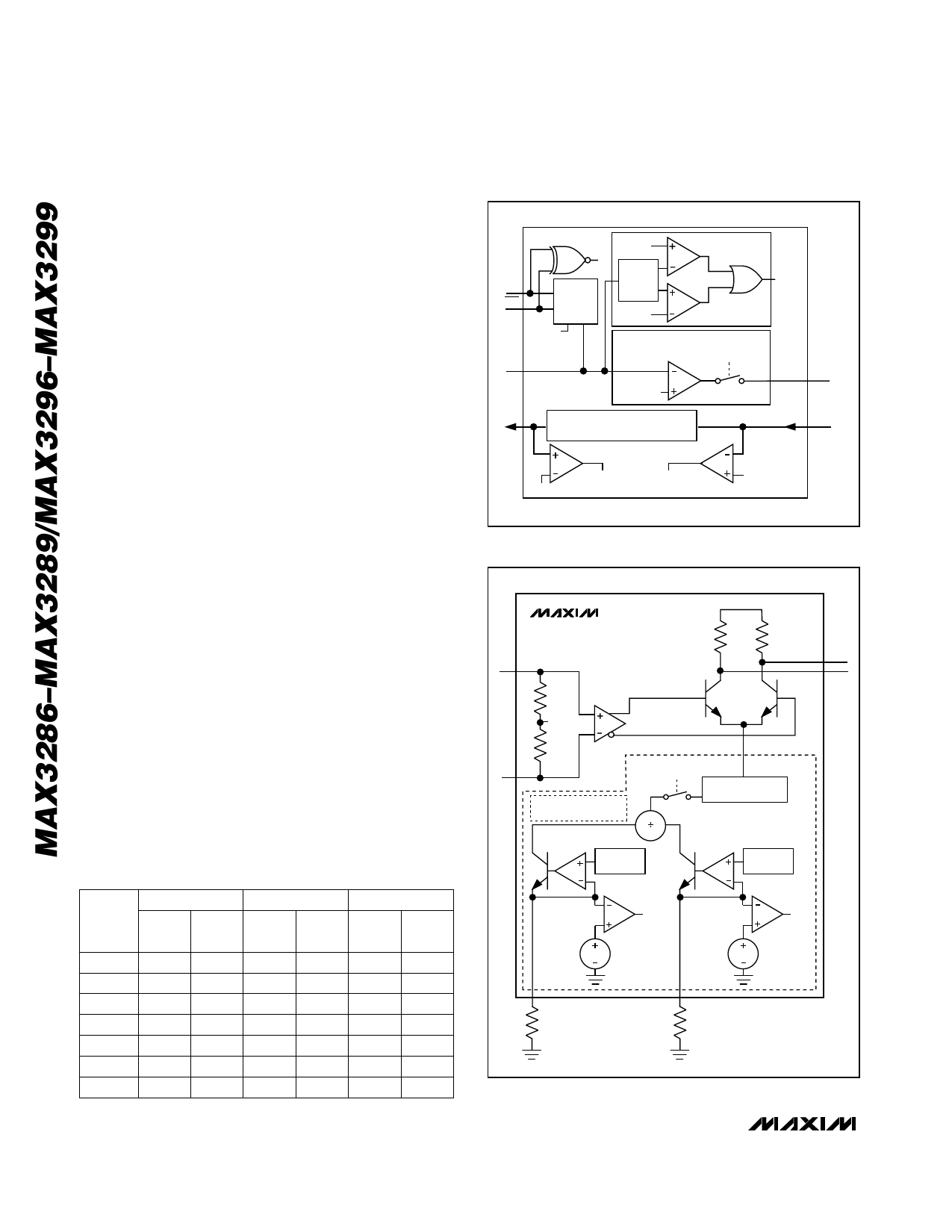
Modulation Circuitry
The modulator circuitry consists of an input buffer, current
generator, and high-speed current switch (Figure 4). The
modulator drives up to 30mA of modulation current into
a 25Ω load.
Many of the modulator performance specifications
depend on the total modulator current (IOUT) (Figure 1a).
To ensure good driver performance, the voltage at
OUT+ and OUT- must not be less than VCC - 1V.
The amplitude of the modulation current is set with
resistors at the MODSET and temperature coefficient (TC)
pins. The resistor at MODSET (RMOD) programs the
temperature-stable portion of modulation current, while
the resistor at TC (RTC) programs the temperature-
increasing portion of the modulation current. Figure 5
shows modulation current as a function of temperature
for two extremes: RTC is open (the modulation current
has zero temperature coefficient) and RMOD is open
(the modulation temperature coefficient is 4000ppm).
Intermediate tempco values of modulation current can
be obtained as described in the Design Procedure sec-
tion. Table 3 is the RTC and RMOD selection table.
Safety Circuitry
The laser driver can be used with two popular safety
systems. APC maintains laser safety using local feed-
back. Safety features monitor laser driver operation and
POLARITY_FAULT
+1.53V
POL
SMOOTH-
POL
START
ENABLE
MD
GLITCH
REJECT
+1.97V
POWER-
CONTROL
AMPLIFIER
+1.7V
MD
FAULT
WINDOW
COMPARATOR
ENABLE
BIASDRV
REF
CONTROLLED REFERENCE VOLTAGE
MON
VREF = 2.65 - 2.25 (VCC - VMON)
2.95V
REF_FAULT MONITOR_FAULT
VCC - 540mV
Figure 3. Bias Generator Circuitry
MAX3286
MAX3296
IN+
INPUT
400Ω BUFFER
VCC - 0.3V
400Ω
IN-
MODULATION CURRENT
GENERATOR
VCC
50Ω 50Ω
CURRENT
SWITCH
ENABLE
CURRENT AMPLIFIER
OUT+
OUT-
Table 3. RTC and RMOD Selection Table
IMOD = 30mA
TEMPCO
(ppm/°C) RMOD RTC
(kΩ) (kΩ)
IMOD = 15mA
RMOD RTC
(kΩ) (kΩ)
IMOD = 5mA
RMOD RTC
(kΩ) (kΩ)
3500 26.7 1.69 53.6 3.65 162 11.5
3000 9.53 2.0 18.7 4.32 57.6 13.3
2500 5.76 2.49 11.3 5.23 34.8 16.2
2000 4.12 3.16 8.06 6.49 24.9 20.0
1500 3.24 4.32 6.19 8.87 19.1 26.7
1000 2.67 6.49 5.11 13.3 15.8 40.2
500 2.26 13.3 4.22 26.7 13.3 80.6
4000ppm/°C
REFERENCE
TC_FAULT
1.2V
REFERENCE
MOD_FAULT
0.8V
0.8V
TC
MODSET
RTC
RMOD
Figure 4. Laser Modulator Circuitry
10 ______________________________________________________________________________________
Share Link: 