MAX1898 Ver la hoja de datos (PDF) - Maxim Integrated
Número de pieza
componentes Descripción
Fabricante
MAX1898 Datasheet PDF : 12 Pages
| |||
Linear Charger for Single-Cell Li+ Battery
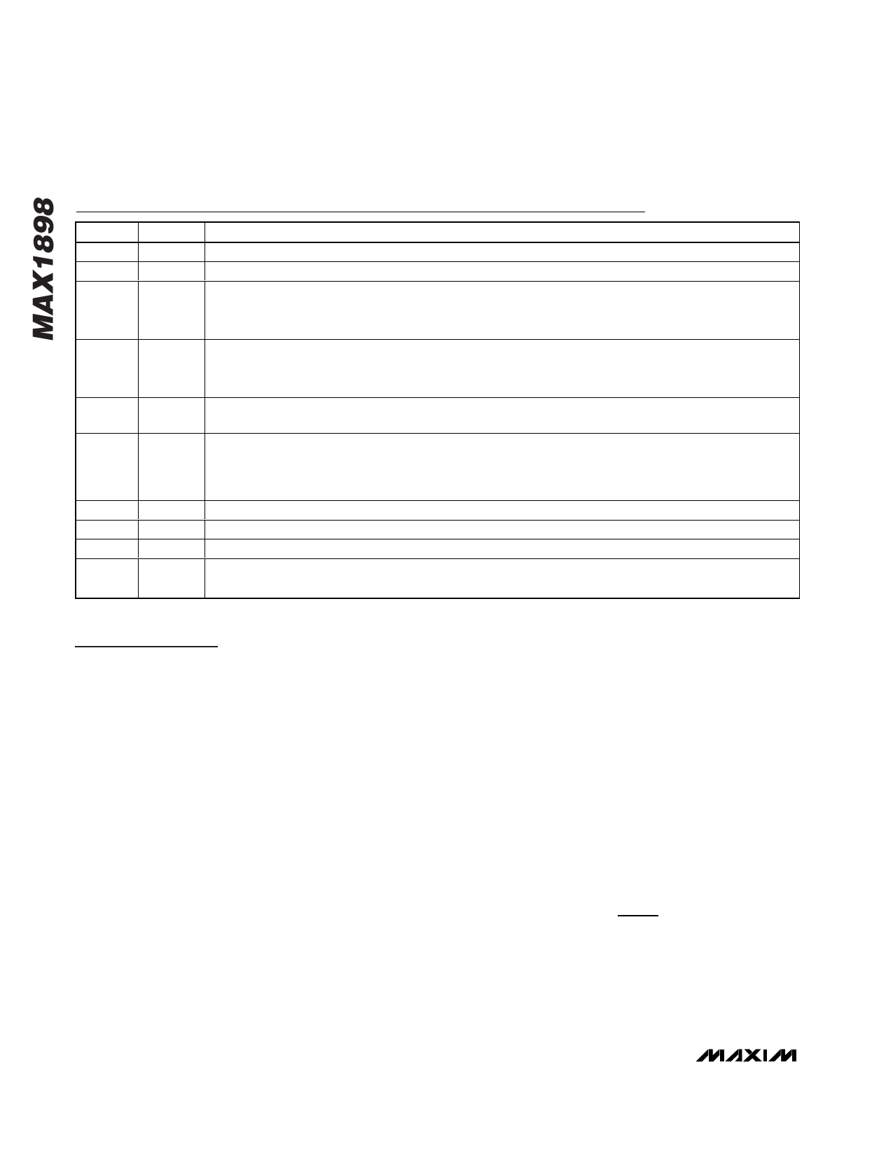
Pin Description
PIN
NAME
FUNCTION
1
IN
Sense Input. Detects power source; positive side of internal current-sense resistor.
2
CHG Open-Drain LED Driver. See Table 1 for CHG output states.
Logic-Level Enable Input and Input Power OK Output. Hold low to disable charger. Float for normal
3
EN/OK operation, drive with an open-drain device to utilize both pin functions, or connect through 10kΩ for logic-
controlled ON/OFF. See the EN/OK (EN Input, OK Output) section for details.
ISET serves two functions. It provides an analog output proportional to the actual charge current. Output
4
ISET current from ISET is 1mA per amp of battery charging current. The charging current is set by connecting a
resistor from ISET to ground. See the Current-Limit Mode section.
5
CT
Safety Charge Timer Control. Connect timer capacitor to program safety time-out interval; 100nF for
approximately three hours. Connect to GND to disable the timer function.
Automatic-Restart Control Pin. When tied to GND, a new charging cycle starts if the cell drops 200mV below
6
RSTRT
the battery regulation threshold. The restart threshold may be lowered by connecting a resistor from RSTRT
to ground. See the Reinitiating a Charging Cycle section. Automatic restart is disabled when RSTRT is
unconnected or when CT is grounded (timer disabled).
7
BATT Battery Sense Input. Positive terminal of single Li+ cell.
8
GND Ground
9
DRV External Transistor Driver. This pin drives the gate/base of an external PMOS/PNP pass transistor.
10
CS
Current-Sense Input. Negative side of internal current-sense resistor. Connect to source/emitter of
PMOS/PNP pass transistor.
Detailed Description
The MAX1898 forms a complete charger for 1-cell Li+
batteries. It includes precision voltage control (±0.75%)
to optimize both cell performance and cycle life.
Factory-set 4.2V (MAX1898EUB42) and 4.1V
(MAX1898EUB41) versions charge all common Li+
chemistries. Externally selectable charge current is
sensed internally, eliminating the need for a current-
sense resistor. The charger also supplies outputs that
indicate charge status (CHG), the presence of input
power (EN/OK), and charge-current magnitude (ISET).
Other features include a shutdown control input
(EN/OK), selectable threshold for charge-cycle restart
without cycling input power (RSTRT), and a selectable
charge termination safety timer. See Figure 1.
The MAX1898 initiates fast charge when any of these
conditions are met (see Figure 6):
• An external power source is connected AND the cell
voltage is above 2.5V.
• The cell voltage falls to the restart threshold, 4.0V in
the MAX1898EUB42, or 3.9V for the MAX1898EUB41.
• The IC is reset by driving the EN/OK pin low and
then high again.
• The prequalification cycle ends with the cell reaching
2.5V.
Li+ cells can be damaged when fast-charged from a
completely dead state. A fully discharged cell may indi-
cate an abnormal cell condition. As a built-in safety fea-
ture, the MAX1898 prequalifies the cell with 10 percent
of the user-programmed fast-charge current at the start
of a charge cycle. When the cell voltage rises to 2.5V,
the MAX1898 begins fast-charging.
Current-Limit Mode
The MAX1898 regulates charging current by linearly
controlling an external PMOS or PNP transistor. The
maximum charging current is programmed by an exter-
nal RSET resistor connected from ISET to GND. Select
the RSET value based on the following formula:
I FASTCHG=
1400V
RSET
where:
IFASTCHG is in amps and RSET is in ohms.
The ISET pin may also be used to monitor the actual
charging current at any time. The output current from
6 _______________________________________________________________________________________
Share Link: 