MAX17498A Ver la hoja de datos (PDF) - Maxim Integrated
Número de pieza
componentes Descripción
Fabricante
MAX17498A
Maxim Integrated

MAX17498A Datasheet PDF : 20 Pages
| |||
MAX17498A/MAX17498B/MAX17498C
AC-DC and DC-DC Peak Current-Mode Converters
for Flyback/Boost Applications
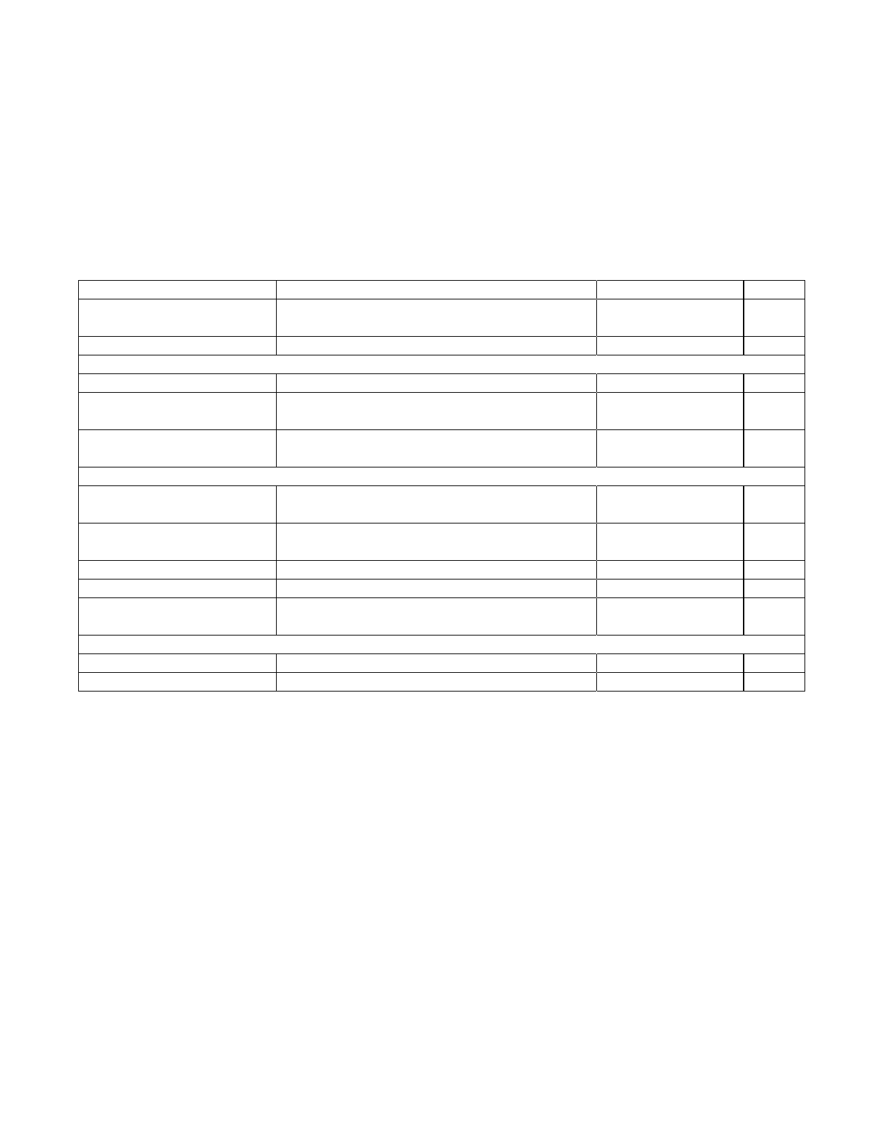
ELECTRICAL CHARACTERISTICS (continued)
(VIN = +15V, VEN/UVLO = +2V, COMP = open, CIN = 1µF, CVCC = 1µF, TA = TJ = -40°C to +125°C, unless otherwise noted. Typical
values are at TA = +25°C.) (Note 1)
PARAMETER
CONDITIONS
Number of Runaway Current-
Limit Hits Before Hiccup Timeout
Overcurrent Hiccup Timeout
SLOPE COMPENSATION (SLOPE)
SLOPE Pullup Current
SLOPE-Compensation Resistor
Range
MAX17498B
Default SLOPE-Compensation
Ramp
SLOPE = open
POWER-GOOD SIGNAL (PGOOD)
PGOOD Output-Leakage
Current (Off State)
VPGOOD = 5V, TA = +25NC
PGOOD Output Voltage
(On State)
IPGOOD = 10mA
PGOOD Higher Threshold
PGOOD Lower Threshold
EA- rising
EA- falling
PGOOD Delay After
EA- Reaches 95% Regulation
THERMAL SHUTDOWN
Thermal-Shutdown Threshold
Thermal-Shutdown Hysteresis
Temperature rising
MIN TYP MAX UNITS
1
#
32
ms
9
10
11
µA
30
150
kI
60
mV/µs
-1
+1
µA
0
0.4
V
93.5 95 96.5
%
90.5 92 93.5
%
4
ms
+160
NC
20
NC
Note 1: All devices are 100% production tested at TA = +25NC. Limits over temperature are guaranteed by design.
Note 2: The MAX17498A is intended for use in universal input power supplies. The internal clamp circuit at IN is used to prevent the
bootstrap capacitor from charging to a voltage beyond the absolute maximum rating of the device when EN/UVLO is low
(shutdown mode). Externally limit the maximum current to IN (hence to clamp) to 2mA (max) when EN/UVLO is low.
Maxim Integrated
4
Share Link: