MAX17498A(2012) Ver la hoja de datos (PDF) - Maxim Integrated
Número de pieza
componentes Descripción
Fabricante
MAX17498A
(Rev.:2012)
(Rev.:2012)
Maxim Integrated

MAX17498A Datasheet PDF : 30 Pages
| |||
MAX17498A / MAX17498B / MAX17498C
AC-DC and DC-DC Peak Current-Mode Converters
for Flyback/Boost Applications
Soft-Start
The devices implement soft-start operation for the
flyback /boost converter. A capacitor connected to the
SS pin programs the soft-start period for the flyback/
boost converter. The soft-start feature reduces the input
inrush current. These devices allow the end user to select
between voltage soft-start usually preferred in nonisolat-
ed applications and current soft-start, which is useful in
isolated applications to get a monotonic rise in the output
voltage. See the Programming Soft-Start of the Flyback/
Boost Converter (SS) section.
Spread-Spectrum Factory Option
For EMI-sensitive applications, a spread-spectrum-
enabled version of the device can be requested from
the factory. The frequency-dithering feature modulates
the switching frequency by Q10% at a rate of 4kHz.
This spread-spectrum-modulation technique spreads
the energy of switching-frequency harmonics over a
wider band while reducing their peaks, helping to meet
stringent EMI goals.
Applications Information
Startup Voltage and Input Overvoltage-
Protection Setting (EN/UVLO, OVI)
The devices’ EN /UVLO pin serves as an enable /disable
input, as well as an accurate programmable input UVLO
pin. The devices do not commence startup operation
unless the EN/UVLO pin voltage exceeds 1.23V (typ).
The devices turn off if the EN/UVLO pin voltage falls
below 1.17V (typ). A resistor-divider from the input DC
bus to ground can be used to divide down and apply a
fraction of the input DC voltage (VDC) to the EN/UVLO
pin. The values of the resistor-divider can be selected
so that the EN/UVLO pin voltage exceeds the 1.23V (typ)
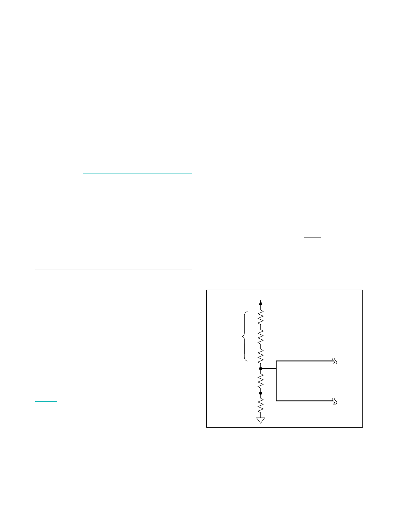
turn-on threshold at the desired input DC bus voltage. The
same resistor-divider can be modified with an additional
resistor (ROVI) to implement input overvoltage protection
in addition to the EN/UVLO functionality as shown in
Figure 2. When voltage at the OVI pin exceeds 1.23V (typ),
the devices stop switching and resume switching opera-
tions only if voltage at the OVI pin falls below 1.17V (typ).
For given values of startup DC input voltage (VSTART),
and input overvoltage-protection voltage (VOVI), the
resistor values for the divider can be calculated as fol-
lows, assuming a 24.9kI resistor for ROVI:
REN=
ROVI ×
VSVTOAVRI T
− 1 kΩ
where ROVI is in kI while VSTART and VOVI are in volts.
R SUM=
ROVI
+ REN×
VSTART
1.23
− 1 kΩ
where REN and ROVI are in kI. In universal AC input
applications, RSUM might need to be implemented as
equal resistors in series (RDC1, RDC2, RDC3) so that
voltage across each resistor is limited to its maximum
operation voltage.
R= DC1
R= DC1
R= DC1
RSUM kΩ
3
For low-voltage DC-DC applications based on the
MAX17498B/MAX17498C, a single resistor can be used
in the place of RSUM, as the voltage across it is
approximately 40V.
VDC
RDC1
RSUM RDC2
RDC3
EN/UVLO
REN
MAX17498A
MAX17498B
OVI
MAX17498C
ROVI
Figure 2. Programming EN/UVLO and OVI
��������������������������������������������������������������� Maxim Integrated Products 11
Share Link: