MAX1661 Ver la hoja de datos (PDF) - Maxim Integrated
Número de pieza
componentes Descripción
Fabricante
MAX1661 Datasheet PDF : 16 Pages
| |||
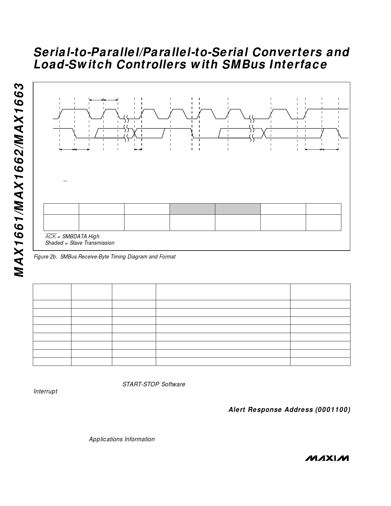
Serial-to-Parallel/Parallel-to-Serial Converters and
Load-Switch Controllers with SMBus Interface
A
B
C
D
EF
G
tLOW tHIGH
SMBCLK
H
I
J
K
SMBDATA
tSU:STA tHD:STA
tSU:DAT
A = START CONDITION
B = MSB OF ADDRESS CLOCKED INTO SLAVE
C = LSB OF ADDRESS CLOCKED INTO SLAVE
D = R/W BIT CLOCKED INTO SLAVE
E = SLAVE PULLS SMBDATA LINE LOW
F = ACKNOWLEDGE BIT CLOCKED INTO MASTER
G = MSB OF DATA CLOCKED INTO MASTER
H = LSB OF DATA CLOCKED INTO MASTER
Receive-Byte Format
ADDRESS
START
CONDITION
7 bits
ACK = SMBDATA High
Shaded = Slave Transmission
READ
1 bit
(high)
ACK
1 bit
(low)
DATA
8 bits
Figure 2b. SMBus Receive-Byte Timing Diagram and Format
tSU:STO tBUF
I = ACKNOWLEDGE CLOCK PULSE
J = STOP CONDITION
K = NEW START CONDITION
ACK
1 bit
(high-Z)
STOP
CONDITION
Table 3. Format for Receive-Byte Data
BIT
7 (MSB)
6
5
4
3
2
1
0
NAME
—
—
—
—
THSD
Data 3
Data 2
Data 1
POR STATE
FUNCTION
0
Not used
0
Not used
0
Not used
0
Not used
N/A
This bit indicates a thermal shutdown.
N/A
This bit indicates the state of I/O3 (high or low).
N/A
This bit indicates the state of I/O2 (high or low).
N/A
This bit indicates the state of I/O1 (high or low).
LATCHED
—
—
—
—
Yes
No
No
No
and with the software START-STOP method (software
interrupts are discussed in the START-STOP Software
Interrupt section). The I/O interrupts can be masked
individually. In addition, the software START-STOP
interrupt can be masked independently. The power-on-
reset state masks the START-STOP interrupt, as well as
the individual I/O interrupts to the ALERT pin (Table 1).
The thermal-shutdown interrupt cannot be masked.
Note that excessive noise on the supply can cause
false interrupts (see Applications Information).
The MAX1661/MAX1662/MAX1663 are slave-only
devices that never initiate communications, except
when asserting an interrupt by forcing ALERT low, or
via the software START-STOP interrupt.
Alert Response Address (0001100)
The Alert Response (interrupt pointer) address pro-
vides quick fault identification for simple slave devices
that lack the complex, expensive logic needed to be a
bus master. When a slave device generates an inter-
8 _______________________________________________________________________________________
Share Link: 