MAX1452 Ver la hoja de datos (PDF) - Maxim Integrated
Número de pieza
componentes Descripción
Fabricante
MAX1452 Datasheet PDF : 25 Pages
| |||
MAX1452
Low-Cost Precision Sensor
Signal Conditioner
VDD
VDD
IRO
DAC
MAX1452
BIAS
GENERATOR
OSCILLATOR
CLK1M
TEST
INP
∑
PGA
OUT
INM
ISRC
BDR
VDDF
DIO
UNLOCK
AMP+
AMP-
CURRENT
SOURCE
TEMP
SENSOR
8-BIT ADC
INTERNAL
EEPROM
6144 BITS
416 BITS
FOR USER VDD
ANAMUX
A=1
FSOTC
176
TEMPERATURE
LOOK UP
POINTS FOR
OFFSET AND
SPAN.
BDR OP-AMP
AMPOUT
VSS
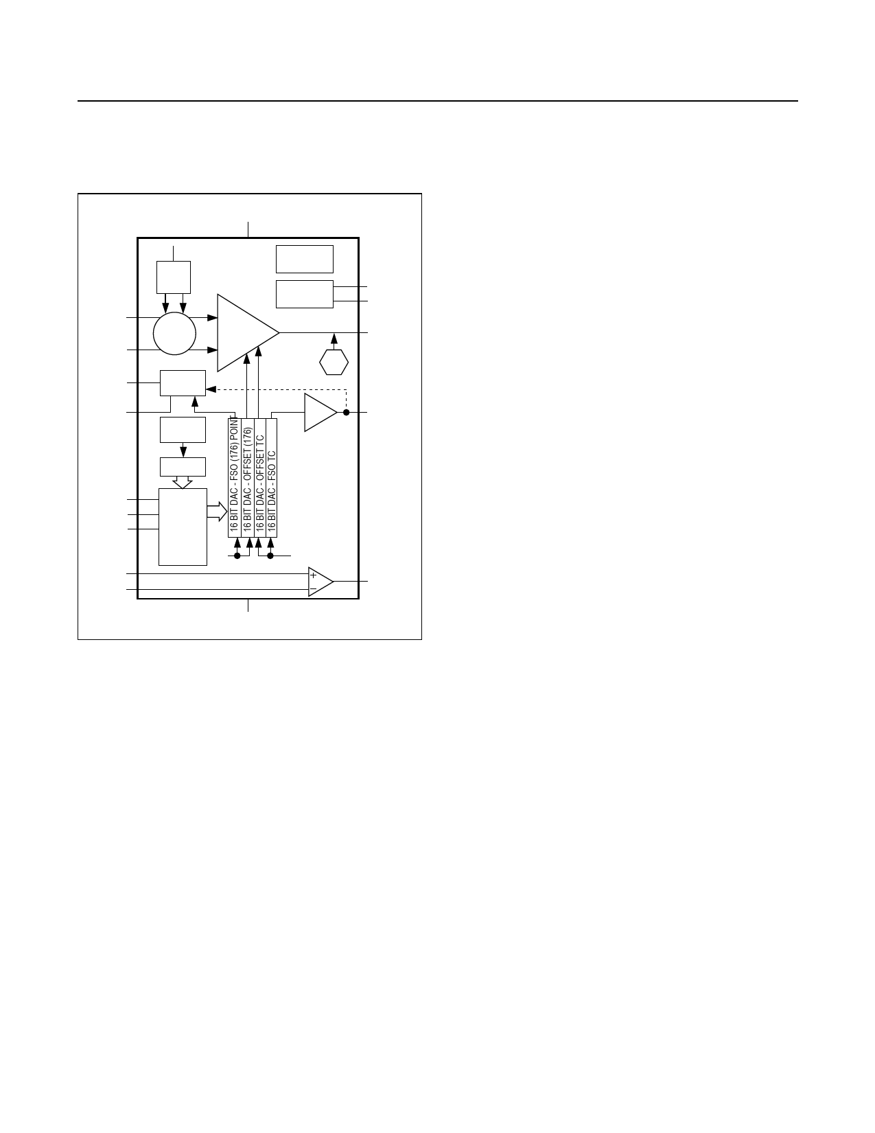
Figure 1. Functional Diagram
or voltage. The PGA utilizes a switched capacitor CMOS
technology, with an input-referred offset trimming range of
more than ±150mV with an approximate 3μV resolution
(16 bits). The PGA provides gain values from 39V/V to
234V/V in 16 steps.
The MAX1452 uses four 16-bit DACs with calibration
coefficients stored by the user in an internal 768 x 8
EEPROM (6144 bits). This memory contains the following
information, as 16-bit wide words:
● Configuration Register
● Offset Calibration Coefficient Table
● Offset Temperature Coefficient Register
● FSO (Full-Span Output) Calibration Table
● FSO Temperature Error Correction Coefficient Register
● 52 bytes (416 bits) uncommitted for customer pro-
gramming of manufacturing data (e.g., serial number
and date)
Offset Correction
Initial offset correction is accomplished at the input stage
of the signal gain amplifiers by a coarse offset setting.
Final offset correction occurs through the use of a tem-
perature indexed lookup table with 176 16-bit entries.
The on-chip temperature sensor provides a unique 16-bit
offset trim value from the table with an indexing resolu-
tion of approximately 1.5°C from -40°C to +125°C. Every
millisecond, the on-chip temperature sensor provides
indexing into the offset lookup table in EEPROM and
the resulting value transferred to the offset DAC register.
The resulting voltage is fed into a summing junction at
the PGA output, compensating the sensor offset with a
resolution of ±76μV (±0.0019% FSO). If the offset TC
DAC is set to zero then the maximum temperature error
is equivalent to one degree of temperature drift of the
sensor, given the Offset DAC has corrected the sensor
at every 1.5°C. The temperature indexing boundaries
are outside of the specified Absolute Maximum Ratings.
The minimum indexing value is 00hex corresponding to
approximately -69°C. All temperatures below this value
output the coefficient value at index 00hex. The maximum
indexing value is AFhex, which is the highest lookup table
entry. All temperatures higher than approximately 184°C
output the highest lookup table index value. No indexing
wraparound errors are produced.
FSO Correction
Two functional blocks control the FSO gain calibration.
First, a coarse gain is set by digitally selecting the gain
of the PGA. Second, FSO DAC sets the sensor bridge
current or voltage with the digital input obtained from a
temperature-indexed reference to the FSO lookup table
in EEPROM. FSO correction occurs through the use of a
temperature indexed lookup table with 176 16-bit entries.
The on-chip temperature sensor provides a unique FSO
trim from the table with an indexing resolution approach-
ing one 16-bit value at every 1.5°C from -40°C to +125°C.
The temperature indexing boundaries are outside of the
specified Absolute Maximum Ratings. The minimum
indexing value is 00hex corresponding to approximately
-69°C. All temperatures below this value output the coef-
ficient value at index 00hex. The maximum indexing
value is AFhex, which is the highest lookup table entry.
All temperatures higher than approximately 184°C output
the highest lookup table index value. No indexing wrap-
around errors are produced.
www.maximintegrated.com
Maxim Integrated │ 7
Share Link: 