MAX1452AAE(2001) Ver la hoja de datos (PDF) - Maxim Integrated
Número de pieza
componentes Descripción
Fabricante
MAX1452AAE Datasheet PDF : 24 Pages
| |||
Low-Cost Precision Sensor
Signal Conditioner
SENSOR
G 2N4392
5
BDR
6 INP
7
VDD
9
VDDF
OUT 2
MAX1452
FSOTC
16
4 INM
ISRC 1
TEST VSS
83
IN 1
MAX6105
2 5V
GND
1kΩ
3
RSTC
0.1µF 0.1µF
RISRC
0.1µF
SD
0.1µF
VPWR
+12V TO +40V
OUT
GND
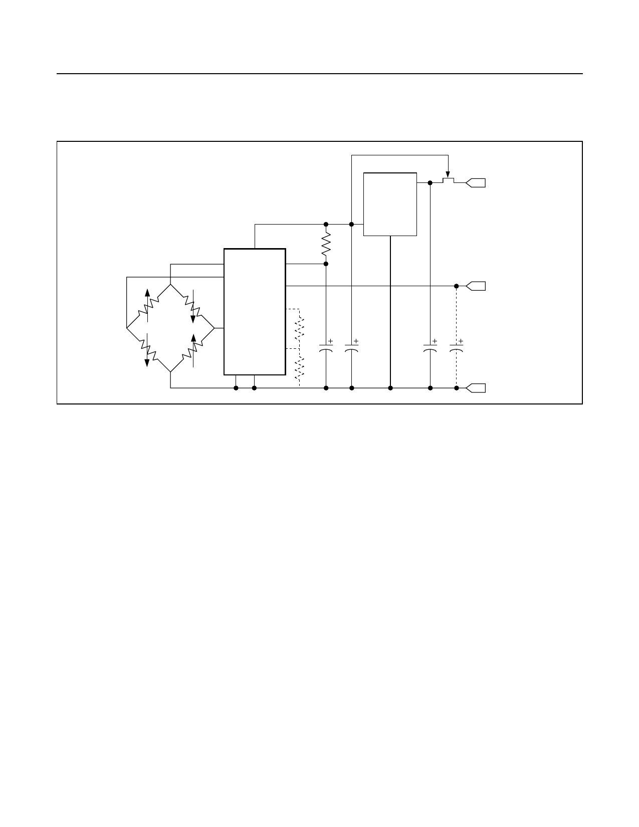
Figure 3. Basic Nonratiometric Output Configuration
Typical Nonratiometric
Operating Circuit
(12VDC < VPWR < 40VDC)
Nonratiometric output configuration enables the sensor
power to vary over a wide range. A high performance
voltage reference, such as the MAX6105, is incorporat-
ed in the circuit to provide a stable supply and refer-
ence for MAX1452 operation. A typical example is
shown in Figure 3. Nonratiometric operation is valuable
when wide ranges of input voltage are to be expected
and the system A/D or readout device does not enable
ratiometric operation.
Typical 2-Wire, Loop Powered,
4–20mA Operating Circuit
Process Control systems benefit from a 4–20mA current
loop output format for noise immunity, long cable runs,
and 2-wire sensor operation. The loop voltages can
range from 12VDC to 40VDC and are inherently nonra-
tiometric. The low current consumption of the MAX1452
allows it to operate from loop power with a simple
4–20mA drive circuit efficiently generated using the
integrated uncommitted op amp (Figure 4).
Internal Calibration Registers (ICRs)
The MAX1452 has five 16-bit internal calibration regis-
ters that are loaded from EEPROM, or loaded from the
serial digital interface.
Data can be loaded into the internal calibration regis-
ters under three different circumstances.
Normal Operation, Power-On Initialization Sequence
• The MAX1452 has been calibrated, the Secure-
Lock byte is set (CL[7:0] = FFhex) and UNLOCK is
low.
• Power is applied to the device.
• The power-on reset functions have completed.
• Registers CONFIG, OTCDAC, and FSOTCDAC are
refreshed from EEPROM.
• Registers ODAC, and FSODAC are refreshed from
the temperature indexed EEPROM locations.
Normal Operation, Continuous Refresh
• The MAX1452 has been calibrated, the Secure-
Lock byte has been set (CL[7:0] = FFhex) and
UNLOCK is low.
• Power is applied to the device.
• The power-on reset functions have completed.
• The temperature index timer reaches a 1ms time
period.
_______________________________________________________________________________________ 9
Share Link: 