IMP522 Ver la hoja de datos (PDF) - IMP, Inc
Número de pieza
componentes Descripción
Fabricante
IMP522 Datasheet PDF : 6 Pages
| |||
IMP522
Application Information
Power Sequencing
To power up the chip, the RSW-OSC pin is connected to VDD through
the external RSW resistor. The voltage on the pin will charge up to
VDD/2. An internal threshold detector circuit monitors the pin
voltage and when it exceeds the threshold range (0.2V to 0.9V) it
powers up the oscillator and internal bias modules. This starts a
delay counter which is one half of the EL oscillator period, after
which power to the high voltage internal modules is applied. The
IMP522 is then operating fully.
To power down the chip, RSW is driven to ground via a switch or
logic gate. When the voltage on the driver side of the resistor falls
below VDD/2, there will be no input bias current into the RSW-OSC
pin. This immediately powers down the internal high-voltage
circuits, which effectively shuts the lamp off. At this point the
oscillator and bias modules still draw quiescent current, but oscil-
lations have ceased. As the RSW-OSC pin voltage falls below 0.1, the
oscillator and bias modules are also fully powered down.
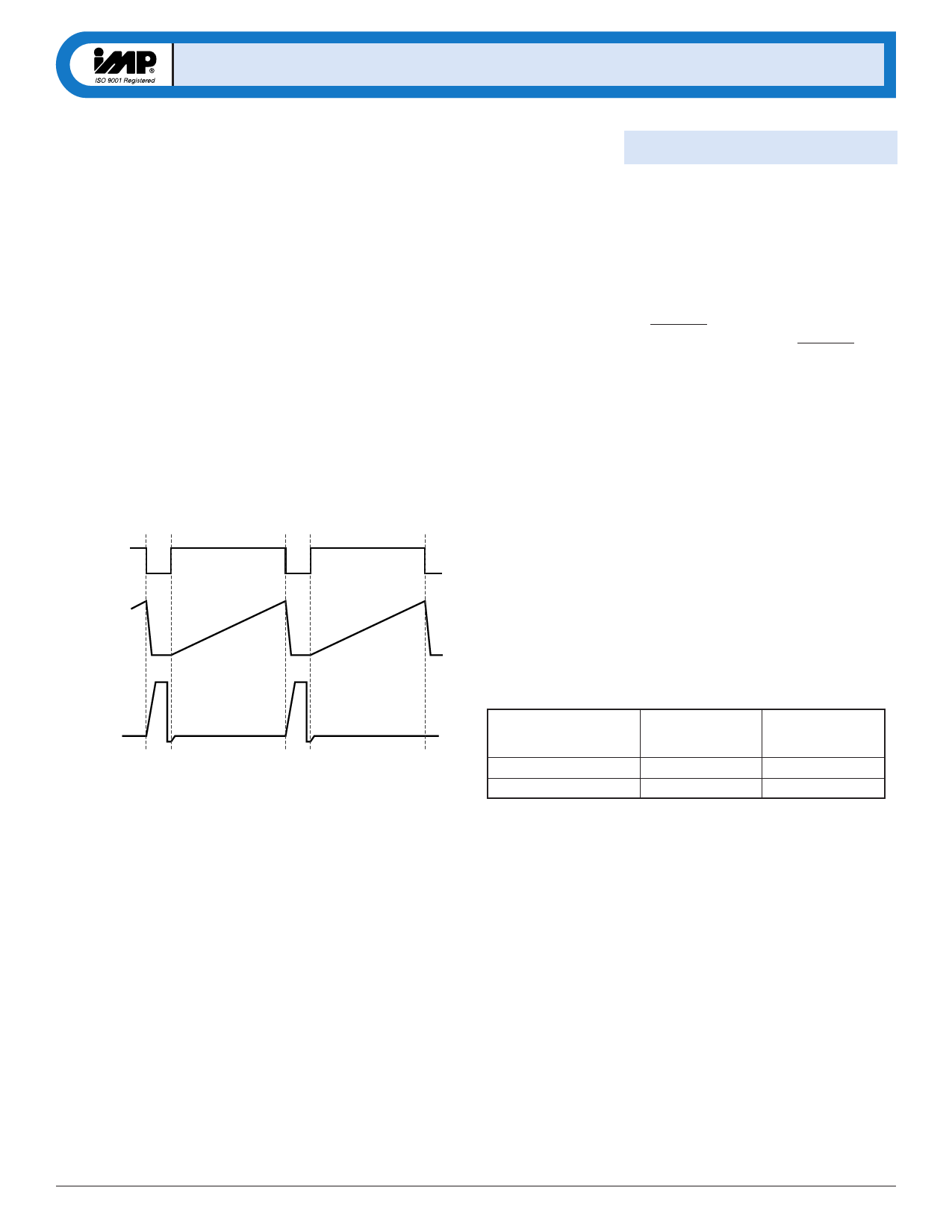
IN (Pulse)
Power Saving Disable Mode
The IMP522 can be powered up and down with RSW-OSC. In
normal operation, this resistor on the RSW-OSC pin is connected to
VDD or another voltage source. To power down (disable) the
IMP522, RSW is connected to ground.
When disabled, the IMP522 quiescent current drops to typically 20nA.
In die form, an extra pin ENABLE is available (contact factory).
Connecting this pad to VDD disables the chip. The ENABLE signal
can be driven by a microcontroller.
Oscillator Frequency Adjustment
The EL lamp drive and PWM boost converter oscillation frequen-
cies can be programmed independently.
The RSW resistor, connected between the RSW-OSC pin and VDD,
determines the Inductor Switching (or PWM-) frequency. For the
recommended nominal resistor value of 910kΩ, the frequency is
61kHz. For other resistor values, the frequency is inversely pro-
portional to the resistor value. Increasing the resistance will lower
the frequency.
ILX
VLX
Figure 1. Driver Waveforms
522_03.eps
The REL resistor, connected between the REL-OSC pin and VDD,
determines the EL lamp drive frequency. For the recommended
nominal resistor value of 2.7MΩ, the frequency is 250Hz. For
other resistor values, the frequency is inversely proportional to
the resistor value: increasing the resistance will lower the fre-
quency.
Oscillator
EL Lamp Drive
Inductor Switch (PWM)
Nominal
Resistor
REL = 2.7MΩ
RSW = 910kΩ
Nominal
Frequency
250Hz
61kHz
522_t03.eps
© 2001 IMP, Inc.
Electroluminescent Lamp Drivers
5
Share Link: 