IMP522 Ver la hoja de datos (PDF) - IMP, Inc
Número de pieza
componentes Descripción
Fabricante
IMP522 Datasheet PDF : 6 Pages
| |||
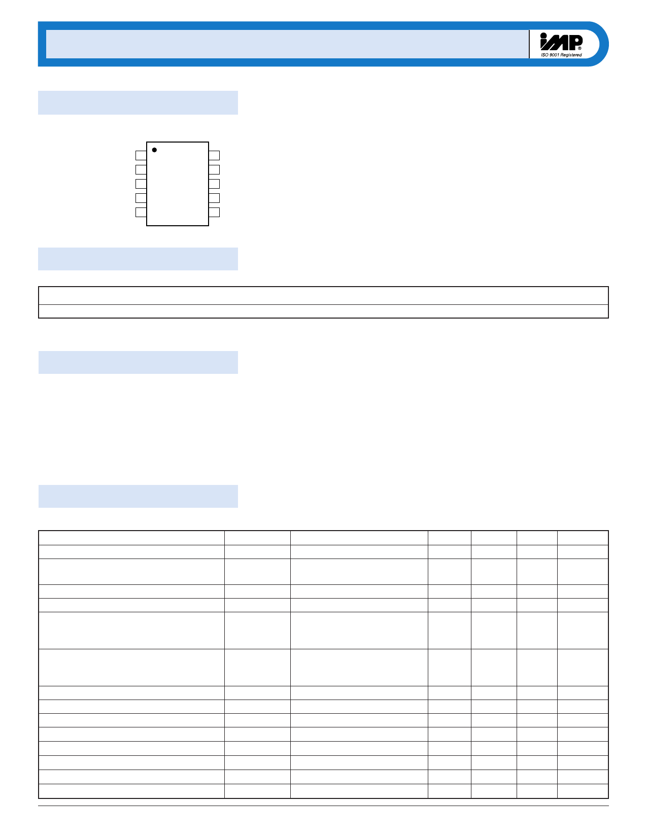
IMP522
Pin Configuration
MicroSO
VDD 1
RSW-OSC 2
CS 3
LX 4
VB 5
IMP522
10 REL-OSC
9 LMPSEL
8 VA
7 VAB
6 GND
522_02.eps
Ordering Information
Part Number
Input Voltage
IMP522EMB
2.0V to 6.5V
Add /T to ordering part number for Tape and Reel.
Temperature Range
– 40°C to +85°C
Pins - Package
10-MicroSO
Absolute Maximum Ratings
VDD, RSW-OSC and REL-OSC . . . . . . . . . . . . . . . . . –0.5V to +7.0V
CS, LX . . . . . . . . . . . . . . . . . . . . . . . . . . . . . . . . . –0.5V to +120V
Operating Temperature Range . . . . . . . . . . . . –40°C to +85°C
Storage Temperature Range . . . . . . . . . . . . . . –65°C to +150°C
Power Dissipation (MicroSO) . . . . . . . . . . . . . 500mW
VA, VB, VAB . . . . . . . . . . . . . . . . . . . . . . . . . . . . . –0.5V to VCS (pin 3)
Note: All voltages are referenced to GND.
These are stress ratings only and functional operation is not
implied. Exposure to absolute maximum ratings for prolonged
time periods may affect device reliability.
Electrical Characteristics
Unless otherwise noted, VDD = 3.0V, RSW = 910kΩ, REL = 2.7MΩ, L = 220µH and TA = 25°C.
Parameter
ON-resistance of MOS Switch
Output Voltage Regulation
Symbol
RDS(ON)
VCS
Output Voltage Peak-to-Peak (in regulation)
Input Current at VDD Pin
Powerdown Input Current
VA-VAB, VB-VAB
IDD
IDDQ
Input Crrent Plus Inductor Current
IIN
Output Drive Frequency
Switching Frequency
Switching Duty Cycle
LMPSEL Low-Level Threshold
LMPSEL High-Level Threshold
LMPSEL Input Resistance
LMPSEL Sink/Source Resistance
LMPSEL Hysteresis
fEL
fSW
DSW
VIL
VIH
RLMPSEL
ILMPSEL
Vhys
Conditions
I = 100mA
VDD = 2.0 to 6.5V,
T = –40°C to 85°C
In Regulation
LMPSEL = GND
VRSW–OSC < 100mA
VDD = 2.0 to 6.5
T = –40°C to 85°C
See Figure 1
LMPSEL = GND or VDD
LMPSEL = floating
See Figure 1
See Figure 1
See Figure 1
Floating/Hign Impedance State
2
408-432-9100/www.impweb.com
Min
±5
Typ Max Units
4.0
8.0
Ω
110
120
V
220
V
650
µA
2
µA
30
43
250
61
88
0.3 VDD
0.7 VDD
50
50
mA
mA
Hz
kHz
%
V
V
kΩ
µA
mV
© 2001 IMP, Inc.
Share Link: 